Hydraulic Hose Pressure Drop Calculator
Estimate hydraulic oil pressure drop through a hose assembly using flow, true inside diameter, hose length, oil viscosity, temperature, fittings, Reynolds number, Darcy friction factor, and elevation change.
Pick a common hydraulic hose scenario. Each preset fills service type, oil grade, flow, bore, length, roughness, fittings, oil temperature, and elevation.
| Line service | Common velocity range | Pressure-drop concern | Practical note |
|---|---|---|---|
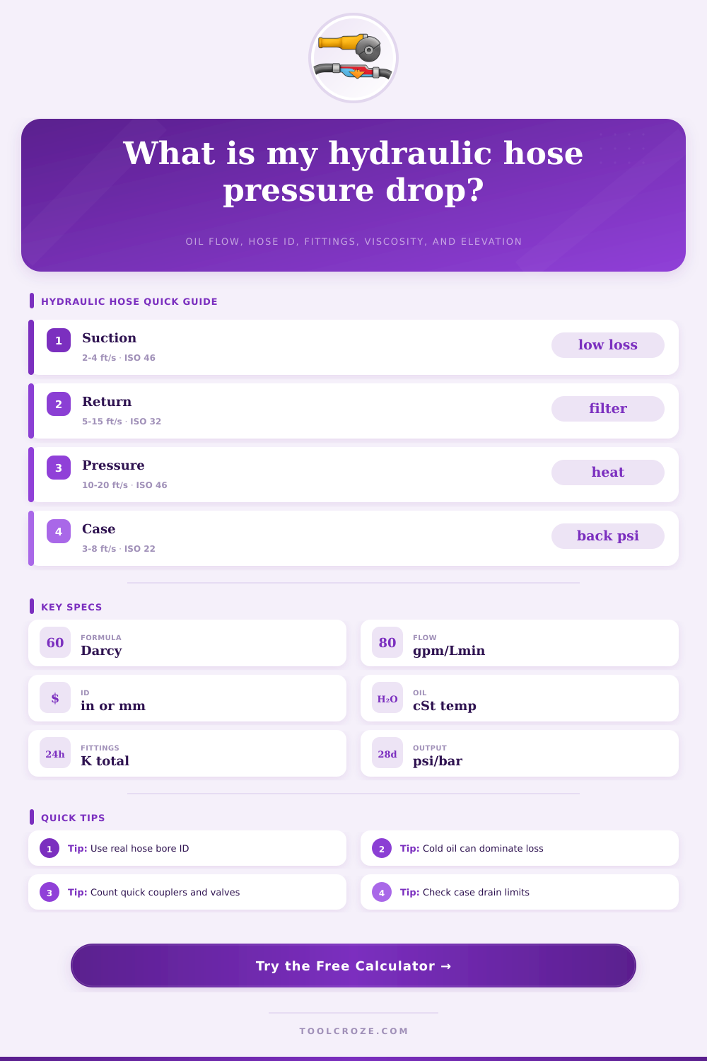
| Suction | 2 to 4 ft/s, 0.6 to 1.2 m/s | Vacuum, cavitation, inlet starvation | Keep short, large, and smooth with very low fitting loss. |
| Return | 5 to 15 ft/s, 1.5 to 4.6 m/s | Filter and cooler backpressure | Watch pressure drop after warm-up and at cold start. |
| Pressure | 10 to 20 ft/s, 3.0 to 6.1 m/s | Heat, pump power loss, noise | Larger ID helps most when pressure loss is a large share of pump margin. |
| Case drain | 3 to 8 ft/s, 0.9 to 2.4 m/s | Motor seal and drain limit | Use the lowest listed backpressure limit from the component data sheet. |
| Pilot or servo | 4 to 12 ft/s, 1.2 to 3.7 m/s | Response lag and small-bore loss | Small hoses can be acceptable at low flow but restrictive at high flow. |
| Cooler loop | 4 to 10 ft/s, 1.2 to 3.0 m/s | Cooler and return manifold drop | Add cooler, filter, thermostat, and valve losses when data is available. |
| Oil grade | Approx cSt at 40 C | Approx cSt at 100 C | Use in calculator |
|---|---|---|---|
| ISO VG 22 | 22 | 4.9 | Light pilot, cold climates, high-speed circuits. |
| ISO VG 32 | 32 | 5.4 | General mobile and industrial hydraulics. |
| ISO VG 46 | 46 | 6.8 | Common default for many power units and mobile machines. |
| ISO VG 68 | 68 | 8.7 | Warmer ambient conditions and older hydraulic systems. |
| ISO VG 100 | 100 | 11.2 | Heavy oil service where cold-start pressure drop can be severe. |
| ATF style fluid | 34 | 7.3 | Transmission or light hydraulic services requiring ATF-like fluid. |
| Fitting or device | Typical K range | Pressure-drop effect | When to enter higher K |
|---|---|---|---|
| Straight adapter | 0.1 to 0.3 | Low | Use higher value when bore steps down sharply. |
| 90 degree elbow | 0.5 to 1.5 | Medium | Compact elbows and tight forged bends are more restrictive. |
| Quick coupler pair | 1.0 to 4.0 | High | Use data sheet pressure drop if the coupler is near rated flow. |
| Ball valve | 0.2 to 2.5 | Low to high | Partial opening or reduced-port valves need higher K. |
| Filter or cooler | Use test data | Variable | Convert known device pressure drop to extra K when possible. |
| Manifold passage | 0.5 to 3.0 | Medium | Add K for sharp drilled intersections and small ports. |
As with every other system, the function of a hydraulic system are based upon the path that the hydraulic oil will take from the pump to the cylinder and from the cylinder back to the pump. The path is typically a hydraulic hose. Every inch of the hose, every fitting on the hose, and every change in the direction of the hose will cause a loss of the pressure of the fluid that moves through the hose.
That lost pressure does not reach the cylinder and the hydraulic motor; the lost pressure becomes heat, causes the system to have slower responses, or puts an overload on the hydraulic pump. Many people attempt to size the hydraulic hoses based off the dash size of the hose. Using only the dash size, however, isnt an accurate method of sizing the hoses for a hydraulic system.
How to Size Hydraulic Hoses
The user should measure the inside diameter of the hose, the user should measure the temperature of the hydraulic oil, and the total resistance of the system that exist in the hoses and the elevation changes should be measured. One of the main variables of a hydraulic system is the temperature at which that system operate. Changes to the temperature of the hydraulic oil alter the viscosity of that oil.
At temperatures that are too cold, the oil becomes thick; oil that moves well at 120 degrees may become nearly blocked at 40 degrees. The hydraulic system calculator allow the user to enter the grade of the oil and the operating temperature of the oil. The viscosity of the hydraulic oil and the temperature of the oil determine the resistance of the oil to the movement within the hydraulic system.
Once these variables are accounted for, the diameter of the hose become the next important variable. When the diameter of the hose is reduced, the velocity of the oil within the hose increases. It is possible that the hose appear to be of adequate size using the dash size; using the actual inside diameter of the hose, however, may reveal that the hoses are too restrictive to allow the required movement of the oil within the system.
Both the fittings and the valves within the system will cause a loss of pressure within the system. Each elbow, quick coupler, and ball valve will contribute to the loss of pressure within the system, but those losses is independent of the length of the hoses. The K factor method calculates the losses due to these components for each component within the system.
You can sum the K factors for each of these components to determine whether the losses in the system are due to the length of the straight hose segments or the number and type of fittings within the system. Changes in elevation within the system will also contribute to the losses in the system; rises in elevation will contribute to an increase in the total system pressure and drops in elevation will contribute to a decrease within the system. The calculator accounts for these changes in elevation within the system.
The calculator also displays the Reynolds number and the Darcy friction factor for the system. The Reynolds number and the Darcys friction factor help to determine the type of fluid movement that will occur within the hoses. At low Reynolds numbers, the oil within the hoses will remain in smooth layers and the viscosity of the oil will be the controlling factor for the movement of the oil.
At high Reynolds factors, the movement of the oil will be turbulent and the roughness of the interior of the hoses will become a contributing factor to the movement of the oil within those hoses. Within the transition zone between these two factors, estimates to the Reynolds and Darcy factors are the least reliable; the calculator displays these estimates but also highlights when these factors are being estimated. The Reynolds and Darcy factors allow a technician or engineer to determine if the system should be warmed to allow for the oil to move more easily or if the diameter of the hoses should be increased.
Two tables is provided on the calculator’s webpage. The first table displays the velocity ranges of fluid within different types of hoses. More specifically, the tables display the recommended velocities within suction lines, return lines, pressure lines, and case drain lines.
The ability of the pump to extract the oil limits the velocities within the suction lines; filters in those return lines limit velocities within the return lines, the heat created by the fluid movement in those lines limits velocities within the pressure lines, and the ability of the system to dissipate the heat created by the system limits velocities within the case drain lines. The other table displays the K factors of different types of fittings. Each fitting within the system will contribute to the pressure loss within the system as described above.
The tables allow the designer of a system to make sure that the velocities and the fittings within the system are within the limits of the systems components. In real installations, hoses become rougher over time and oil within the hoses can become contaminated. Each modification to the system that includes the use of quick couplers can change the flow of fluid within those components.
An allowance for these issues is included in the calculation; different percentages can be used for hoses and systems of different ages and for fluids of different temperatures. An allowance of 10% is often applied to normal service installations; 20% may be used in systems in which the oil will be exposed to cold temperatures or in systems where the fitting data isnt complete or accurate. The calculator displays both the calculated and the allowed pressure drop within the hoses to assist the designer in understanding the impact of these changes.
The calculator answers the question of whether the hydraulic assembly that will be created will remain within the limits of the remainder of the circuit. Components of the system have limits to the pressures that they will experience; these limits include the margin of the pump, the relief valves, the limits of the case drain lines, and the filters. Determining whether the pressure drop that will occur in the hoses will remain within those limits for the system; if the limits are exceeded, changes to the system will be required.
Changes to the diameter of the hoses will have the most impact upon the calculations that occur within the calculator. Changes to the length of the hoses or the number of hose fittings will impact the calculations of the system, but in a linear fashion. Changes to the diameter will impact the velocity of the oil within the hoses, the Reynolds number of the system, and the Darcy friction factor within the hoses.
Technicians are often trained to check the actual bore of the hoses after installing the fittings into the hoses; the bore size is the most important measurement of the hose, followed by the measurement of the temperature of the oil that will move within those hoses. The same logic can be applied to situations in which the hydraulic system becomes too hot. The higher the pressure drop within the system, the more work that is required of the pump to convey the oil through the system.
This work is converted to heat within the hydraulic oil. Reducing the pressure drop by better sizing the hydraulic hoses will have a greater impact upon the reduction in the temperature of the system than adding a larger cooler to the system. The calculator also displays the heat load of the system created by the pressure loss at the entered flow.
This number can help the designer of the system to determine whether the amount of extra horsepower that is required to overcome the resistance of the system and the amount of heat that is created are acceptable, or whether changes are required to the hydraulic hose assembly. The goal of the system is to have a hydraulic hose of the correct diameter and length that can deliver the required amount of flow from the pump to the cylinder at an acceptable pressure. The pressure drop within the hoses should remain within the limits of the temperature limits and velocity limits of the components of the system.
Furthermore, the calculator removes the need to perform the arithmetic calculations within the system; instead of making engineering and design decisions using only your head, the calculator allows the engineers and technicians to make those same decisions using numbers.