H7 Tolerance Calculator
Calculate ISO hole limits, shaft limits, and fit behavior for precision reamed parts.
Calculation breakdown
| Nominal diameter | -- |
| Diameter band / D | -- |
| Tolerance unit i | -- |
| Hole tolerance width | -- |
| Shaft tolerance width | -- |
| Hole limits | -- |
| Shaft limits | -- |
| Theoretical clearance range | -- |
| Finish stock estimate | -- |
| Actual fit status | -- |
| Diameter band | Geometric mean D | IT7 width | Notes |
|---|---|---|---|
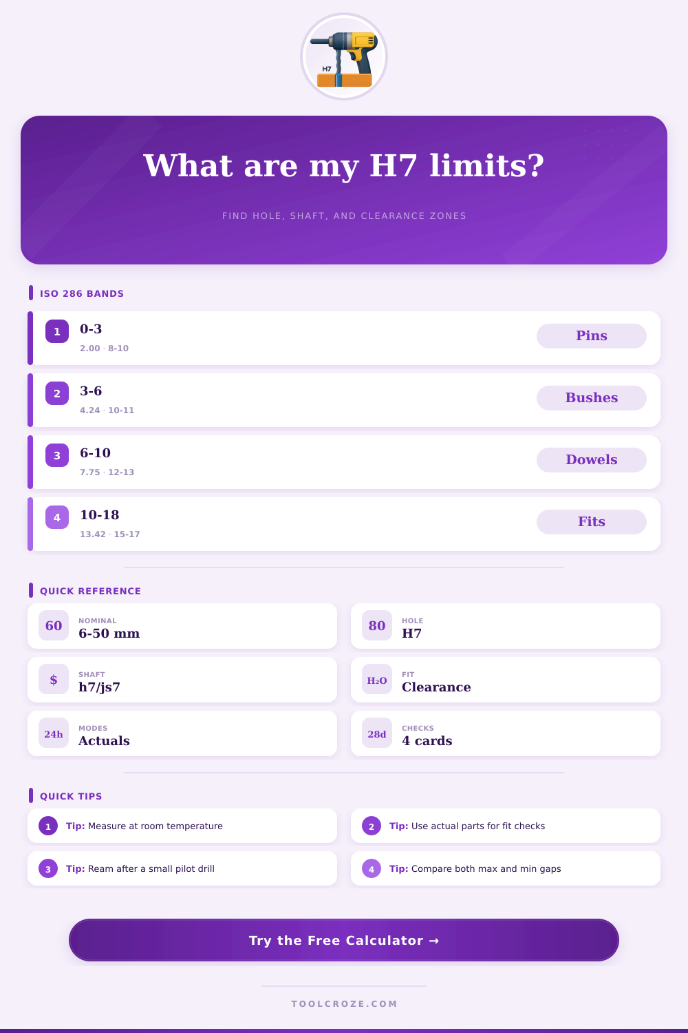
| 0 to 3 mm | 2.000 mm | about 10 µm | Small pins and locating dowels |
| >3 to 6 mm | 4.243 mm | about 11 µm | Tight small bush and hinge fits |
| >6 to 10 mm | 7.746 mm | about 13 µm | Common precision drill and pin work |
| >10 to 18 mm | 13.416 mm | about 16 µm | Shop reamers and tooling shafts |
| >18 to 30 mm | 23.237 mm | about 19 µm | Fixture bores and medium shafts |
| >30 to 50 mm | 38.730 mm | about 22 µm | Hardware, hubs, and guide pins |
| >50 to 80 mm | 63.246 mm | about 25 µm | Large collars and machine parts |
| >80 to 120 mm | 97.980 mm | about 29 µm | Heavy-duty fit and alignment work |
| Pair | Clearance window | Typical use | Fit type |
|---|---|---|---|
| H7 / h7 | 0 to IT sum | Locating dowels | Clearance |
| H7 / js6 | Centered | Snug assembly | Transition |
| H7 / js7 | Near zero | Careful slip fit | Transition |
| H7 / h6 | Slightly open | Precision pins | Clearance |
| H8 / h7 | More open | Free-running fit | Clearance |
| H7 / h8 | More open | Easy assembly | Clearance |
| Sample size | H7 hole min-max | h7 shaft min-max | Practical note |
|---|---|---|---|
| 6 mm | 6.000-6.011 | 5.989-6.000 | Popular dowel size |
| 8 mm | 8.000-8.014 | 7.986-8.000 | Tooling and guides |
| 10 mm | 10.000-10.016 | 9.984-10.000 | Fixtures and bushings |
| 12 mm | 12.000-12.016 | 11.984-12.000 | Workshop alignment |
| 16 mm | 16.000-16.018 | 15.982-16.000 | Heavier parts |
| 25 mm | 25.000-25.020 | 24.980-25.000 | Large bore fit |
| Process | Target before finish | Watch for | Best result |
|---|---|---|---|
| Drill | 0.10-0.30 under | Runout | Ream after drilling |
| Ream | Near nominal | Chip load | Clean H7 hole |
| Turn | 0.02-0.08 over | Tool wear | Ground or skim finish |
| Grind | Very near nominal | Heat | Stable shaft size |
| Gauge | Check limits | Temperature | Room-temperature reading |
| Press | Measure first | Surface damage | Repeatable assembly |
Making processes always have changes. Without big costs almost cannot reach exact sizes. So each shown size for part includes right errors.
You commonly show them by means of H7 tolerance. In system based on holes, the H shows hole with zero bottom change. That means, that the bottom size matches exactly the normal size.
H7 Hole and How a Shaft Fits
For example, 20 mm H7-hole must have at least 20.000 mm. If the size is 19.998 mm, it goes past the tolerance of below.
H7-code uses letter and number to show the limits. Big letters like H7 relate to holes, so to inside sizes. Small letters, like h7, point places, for example shafts.
The number 7 tells the grade of rightness. It shows, is the limit tight or wide, so defines the range of tolerance. Simply said, H7 allow the hole be only a bit bigger than the base, but never less.
Holes in CNC parts are also important as threads. Parts usually put with others. Their link depends on the fitting type.
For example part with H7-hole: for 50 mm the range are 0 until +0.025 mm, so of 50.000 mm until 50.025 mm. Here the hole never gets smaller than the base. For 50 mm H7-hole you write +25, -0 micrometers.
If shaft of 50 mm has g6 tolerance, it goes of -9 until -25 micrometers.
You use various tools and rules for check the sizes. H7-reamer helps that. Some reamers are ground to the best tolerance when they are new, like this they cut a lot.
Charts of H- and h-changes show according to ISO 286-1:2010. They help to find tolerances for bolts and holes. Note, that those charts do not think about position or other GD&T tolerances.
H7-hole with right shaft gives skill in pushing. That results in clear amount of pushing between the parts.