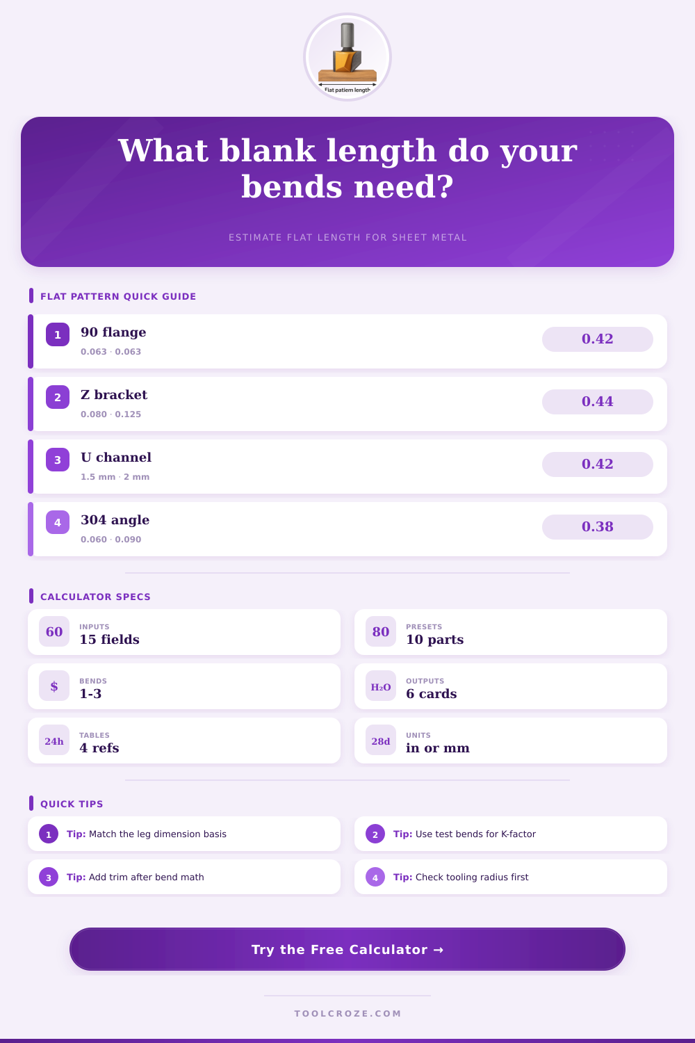
Flat Pattern Length Calculator
Estimate sheet metal blank length from leg lengths, bend angles, inside radius, material thickness, K-factor, bend allowance, bend deduction, multiple bends, and trim allowance.
Choose a common bracket, channel, cover, or tray setup, then fine tune the dimensions for your brake, material, and shop standard.
Flat Pattern Results
| Material | Suggested K | Inside radius guide | Springback note |
|---|---|---|---|
| Mild steel sheet | 0.42 | 1.0T to 1.5T | Predictable with shop tables |
| 304 stainless sheet | 0.38 | 1.5T to 2.0T | Higher springback than mild steel |
| 5052 aluminum | 0.42 | 1.0T to 1.5T | Good formed aluminum baseline |
| 6061 aluminum | 0.40 | 2.0T to 3.0T | Use larger radius to reduce cracking |
| Copper sheet | 0.44 | 0.8T to 1.2T | Soft material; verify with sample |
| Formula | Use when | Expression | Shop meaning |
|---|---|---|---|
| Bend allowance | Tangent lengths | A rad × (R + K × T) | Arc added along neutral axis |
| Setback | Outside dimensions | tan(A / 2) × (R + T) | Distance from mold point to tangent |
| Bend deduction | Outside dimensions | 2 × SB - BA | Amount removed from outside leg sum |
| Flat length | Outside legs | Leg sum - total BD + trim | Common brake layout length |
| Flat length | Tangent legs | Leg sum + total BA + trim | Neutral-axis developed length |
| Preset part | Typical bends | Leg basis | Why it matters |
|---|---|---|---|
| Angle bracket | 1 bend at 90 deg | Outside | Most print dimensions call out flange outsides |
| U channel | 2 bends at 90 deg | Outside | Both side flanges subtract bend deductions |
| Z clip | 2 opposite 90 deg bends | Outside | Offset height depends on tooling radius |
| Tray side blank | 3 bends at 90 deg | Tangent | Many layouts measure straight wall sections |
| Architectural cover | 2 to 3 bends | Outside | Visible face length usually controls fit |
| Thickness | Light gauge radius | General radius | Conservative radius |
|---|---|---|---|
| 0.040 in / 1.0 mm | 0.040 in / 1.0 mm | 0.063 in / 1.6 mm | 0.080 in / 2.0 mm |
| 0.063 in / 1.6 mm | 0.063 in / 1.6 mm | 0.094 in / 2.4 mm | 0.125 in / 3.2 mm |
| 0.080 in / 2.0 mm | 0.080 in / 2.0 mm | 0.125 in / 3.2 mm | 0.160 in / 4.0 mm |
| 0.125 in / 3.2 mm | 0.125 in / 3.2 mm | 0.188 in / 4.8 mm | 0.250 in / 6.4 mm |
Every good sheetmetal job hinges on one thing: getting the length of the flat pattern correct. Get that wrong and your tray sides will buckle or your brackets is too short. Or worse, you’ll waste time and extra material trying to fix mistakes that could of been avoided by getting the length right from the start. Knowing the behavior of bend allowance & bend deduction in the shop are the difference between a clean fit and a pile of scrap.
This is about sheet metal. If I have a sheet of sheet metal, when I form it, it’s stretching on the inner radius and compressing on the outer radius. There’s a line somewhere in the middle that doesn’t stretch or shrink (that’s called the neutral axis). It’s expressed as a percentage of thickness which is what the K-factor tells you. For instance, if the K-factor is 0.42, then it will be located approximately 42 percent of the way through the material. This happens until you see a test bend come up short by two millimeters and learn that your K-factor was actualy wrong by a few hundredths. That slight change affect the whole flat length.
How to Get Sheet Metal Length Right
The main point of argument at the brake concern leg length basis. Some prints is dimensioned from the outside mold line (that’s what fits to another part). Some are dimensioned from a straight tangent length (that’s what the layout guy can actualy scribe on the flat blank). Either approach work fine with the calculator; just choose the correct basis. Mixing approaches will be the quickest route to doubling up on bend deductions or overlooking one completely. Choose one system and stick with it, it keeps the math clean.
The other thing few folks talk about is inside radius. The tighter it is the more springback you will get and the more it moves the neutral axis. But with soft copper, a nice big radius hardly bother the metal at all. Generally speaking, your tooling determine this radius prior to any calculations. Which is another reason it makes sense to check die chart first to save your head. Sometimes the same piece of stock in.063 inches thick calls for a 1T radius on mild steel yet 2.5T or greater on titanium if you don’t want to crack the stuff.
The other thing to consider is how bend count changes the game. If it’s just a simple 90-degree flange, fine; no big deal. But if it’s a Z-clip or a three-bend tray, that multiply any mistake. Each bend adds or subtract from the allowance. The final allowance for trim at the end allow you to account for weld prep or shearing cleanup without having to guess. If there’s negative trim, you can even subtract length afterward, if the final trimming called for in your print requires it.
Every choice comes back to material. Aluminum require a greater radius to avoid orange peel. Stainless has more springback than mild steel. Copper flows so well that if you change grain direction, it make your K-factor float. That’s why experienced shops maintain a stack of test coupons, one for each new combo of brake setup, alloy and thickness. On paper they all look close, but in the real world, flat length can be surprisingly different than expected.
What does that get you on the output? It gives you more than just one blank length. The total bend allowance show you exactly how much arc length the neutral axis contributes. The total bend deduction tell you how much you have to remove from the combined lengths of the outside legs. The neutral axis radius bring it all together. This lets you compare your assumptions against what is actualy going to happen at press brake. These six values sitting in front of you will make the blank size stop being a mystery and become a deliberate decision.
Ultimately though, experienced fabricators consider the flat pattern to be a conversation with the material, the print, the tooling and the experience. Arithmetic is left up to the calculator, while you get to use your judgement on the calls that no equation can provide. Run the numbers, cut a test piece, measure what’s really going on, and adjust accordingly. That loop is what converts theoretical lengths into fitting first-time parts.