If you’re building some sort of machine with shafts and want something to make it move smoothy, select a flange bearing. A flange bearing has a built-in mounting flange on it allowing you to simply bolt it down to a plate without requiring additional housing part.
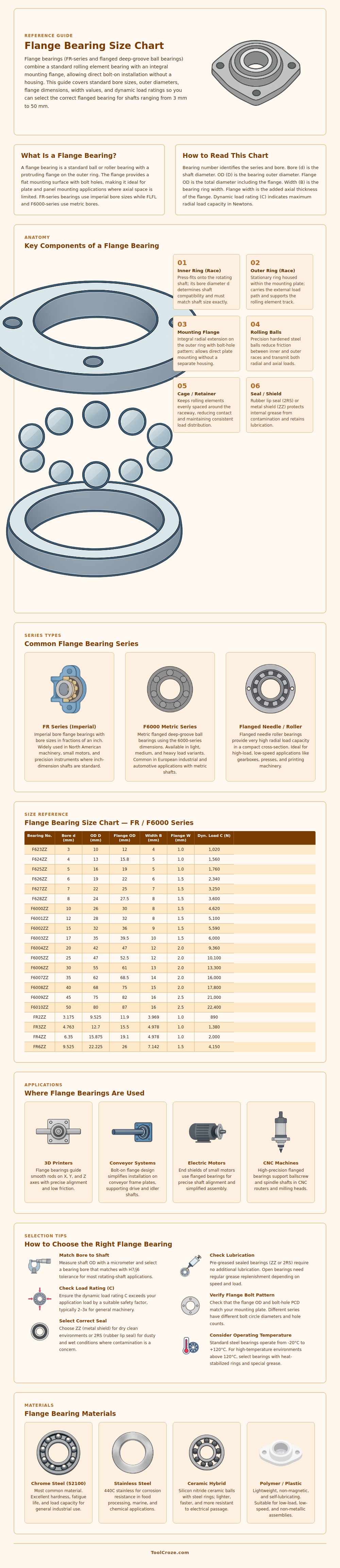
So how do you figure out which one is right? Well that’s where having a good size reference comes in. Match up the size of the bearing to the shaft, the desired load, and whatever space you have available. This chart relates the width, flange diameter, outer diameter, bore size, and load rating across common series. It’s also listed in both imperial and metric sizes, making it useful for mixed system projects. If you’re not sure whether the outer flange diameter will fit your mounting hole, now you know; all measurements are displayed as actual flange outer diameter. The dynamic load rating column display what radial force the bearing will be able to withstand before it become fatigued. That way, you have a real-world figure with which to judge if it is right for your application.
How to Choose the Right Flange Bearing
So what does all this mean? Now you’re reading the chart confidently and know what everything is. Your shaft is the inside diameter that pushes against your shaft and need to be the same diameter as it is. Your outer ring go into your mounting plate and takes up the load via the rolling elements. The flange comes off of the outer ring with holes drilled in it for you to fasten the whole deal together without adding additional bracket.
So now that you understand their role, you know why flange width is important; it increases axial thickness and impacts where your plate sits compared to the rest of your setup. It is not just about size. Environment determines many of your choices, not only size. In North America, where shaft sizes are typically given in inches, you’ll find Imperial FR bearings a lot. On new machines and European builds using standard metric shafts, you’re more likely to see the metric F6000-series. Needle or roller versions with flanges handles higher radial loads in compact spaces, though they trade some speed capability for that strength. And then there’s materials selection. Most general purpose application use chrome steel; marine/food environments require stainless for corrosion resistance. For high-speed spindles, ceramic hybrids can eliminates both weight and electrical concerns.
The other thing people forget is that they just look at bore size without regard to mounting to the flange. So they go through the exercise of measuring their shaft and selecting an equal bore only to find out the hole pattern doesn’t align with the holes they have now. The second thing folks forget is they underestimate the risk of contamination. In a clean dry environment, a metal shield is great. But the moment there’s water or dust in the raceway the friction increase rapidly and life goes down. Rubber seals can provide additional protection by adding some drag, but it really comes down to whether you need maximum speed or longevity for your specific use.
One last consideration is temperature range and lubrication. The bearing is built for a wide but narrow range of temperatures. Beyond that, special grease with heat stabilized rings may be necessary. Do not assume that what came from the factory was best. It might have been just enough to get by for a while. On the plus side, pre-lubricated sealed bearings eliminate day-to-day maintenance but should of been inspected periodically to detect signs of premature wear before it can damage other parts of machine.
That’s where the true benefit of having a bearing size reference for flanges comes in: it replaces a few variables with visualized tradeoffs that are less likely to surprise you at assembly time. If you can visualize how load capacity, flange dimensions, and bore sizes aligns, choosing the correct component becomes less of a guessing game and closer to understanding your own constraints.
