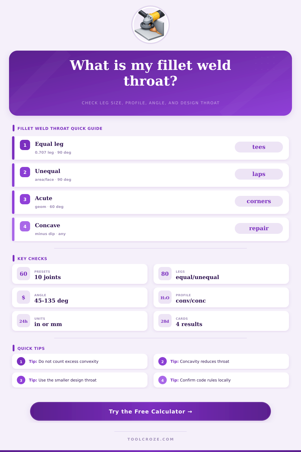
Fillet Weld Throat Calculator
Calculate theoretical throat, effective throat, design throat, and throat area from leg size, unequal legs, included weld angle, concavity, convexity, and root allowance.
Calculation breakdown
| Geometry case | Use this throat model | What changes the result | Shop note |
|---|---|---|---|
| Equal legs, 90 degree included angle | Throat = 0.707 x leg | Leg size, concavity, root allowance | Most common drawing shorthand |
| Unequal legs, any included angle | Altitude from root to weld face | Both leg sizes and included angle | Do not use only the larger leg |
| Convex fillet face | Effective throat ignores excess convexity | Leg geometry still controls design throat | Extra cap may not add design capacity |
| Concave fillet face | Effective throat is reduced by concavity | Depth of dip measured normal to face | Repair may be needed if undersized |
| Preset | Legs | Angle | Profile |
|---|---|---|---|
| Tee Joint 1/4 in Equal Legs | 0.250 x 0.250 in | 90 deg | Flat, 10% design reduction |
| Lap Joint 3/16 in Shop Fillet | 0.188 x 0.188 in | 90 deg | Flat, short double weld |
| Unequal Bracket Fillet | 0.250 x 0.188 in | 90 deg | Unequal legs control throat |
| Metric Unequal Web Clip | 8 x 6 mm | 90 deg | Metric fit-up allowance |
| Check item | Calculator input | Conservative entry | Why it matters |
|---|---|---|---|
| Undersized leg | Leg size A and B | Use measured minimums | Unequal legs lower the altitude |
| Concavity | Profile amount | Measured dip depth | It directly subtracts from throat |
| Convexity | Profile amount | Record but do not count | Most design checks ignore excess cap |
| Root opening | Root allowance | Deduct fit-up loss | Gaps can reduce practical fusion throat |
| Design situation | Suggested reduction | Target throat source | Next check |
|---|---|---|---|
| Controlled shop weld | 0% to 5% | Drawing symbol or WPS | Confirm weld length and end returns |
| Typical fabrication review | 10% | Design calculation or detail note | Check base metal and load path |
| Field fit-up variation | 15% | Inspection requirement | Verify access and fusion quality |
| Rough repair estimate | 20% | Engineer instruction | Do not accept without inspection |
Fillet welds is used to hold structures together. Fillet welds appear at the edges of bracket, clips, and other structural elements. Fillet welds form at the point where one piece of metal meet another piece of metal at either a 90-degree angle or slight skews to one another.
Inspectors do not examine the surface of a fillet weld; instead, the inspector measures the thickness of metal that is working to hold the two pieces of metal together. This thickness are known as the throat thickness of the fillet weld. The thickness of the throat change based off the leg size of the fillet weld.
How to Measure Fillet Weld Throat
The thickness of the throat is measured from the root of the fillet weld to it’s face. When the fillet weld includes each of its leg to 90 degrees from each other, and when each of the legs of the fillet weld is the same length, the thickness of the throat is 0.7 of the length of each leg of the fillet weld. If the legs of the fillet weld are of unequal length, however, the shorter of the two legs determine the length of the throat.
The shorter leg set the limit to how high the altitude is from the root of the fillet weld to its face. A calculator that incorporate fields for the size of each leg of the fillet weld and the included angle between each leg can perform this type of math. In actual fillet welds, the throat often does not sit upon the theoretical line of the fillet weld geometry.
A dip in the face of the fillet weld is referred to as concavity. Concavity shorten the length of the throat. The rounded top of the fillet weld is referred to as convexity.
Convexity do not contribute to the strength of the fillet weld. Concavity and convexity can be entered into a calculator that calculates the throat thickness of the weld. Another element that can reduce the throat thickness is the root gap between the two pieces of metal that is joined together by the fillet weld.
The root gap limits the depth of fusion of the fillet weld, which limits the actual depth of the throat of that fillet weld. Some metal fabrication shops include a root gap field in their throat thickness calculator. These field allow the shop to enter the root gap between the two pieces of metal.
Additionally, a design reduction can be incorporated into the calculation of throat thickness. Some shops include a 10 or 15 percent reduction in the throat thickness calculation to account for variable in the metal drawing that cannot be accounted for in the drawing itself. The angle between the two members of the joint also affect the throat thickness.
If the angle between the two members of the joint is acute, it will reduce the throat thickness of the fillet weld. Even if the legs of the fillet weld are long enough, an acute angle will reduce the throat thickness. Obtuse angles between the members of the joint will increase the throat thickness.
However, obtuse angles also affect how the fillet weld cools and if it is likely to include slag within the fillet weld. For these reason, the user can enter the angle between the two members into a throat thickness calculator instead of making any assumptions about that angle. Throat thickness calculators is capable of calculating throat thickness for angles between 30 and 150 degrees.
The length of the fillet weld does not impact the thickness of the throat, but does impact the total area of throat. If there are two fillet welds of the same size on opposite side of a metal plate, the total area of throat is doubled. The length of the weld may meet the thickness requirement for the fillet weld, but it may not be able to handle the total load that is placed upon the joint.
Throat thickness calculators can incorporate field for length of fillet weld and number of fillet welds at the joint. Common mistake in calculating throat thickness include only considering the length of the visible leg of the fillet weld. The length of the leg of the fillet weld may be long on one side of the weld, but if the leg on the other side of the fillet weld is short, the shorter leg will limit the throat thickness.
Another common mistake is considering the convexity of the fillet weld as a strength in the fillet weld. Most code calculations ignores the height of the convexity of the fillet weld. In both of these instance, a throat thickness calculator can separate the measurement of the face of the fillet weld from the calculation of throat thickness.
Tables exist that display the various case of fillet weld geometry and the requirements for inspecting those fillet welds. These tables are not a replacement for a code book, however. These tables help to display the reasoning for each of the inspection requirements for fillet welds.
These tables also display the conservative measure to the throat thickness calculation. For example, field welds that may have variable fit up of the metal plates will have a different design reduction in their throat thickness calculation than welds that are fabricated in a shop with quality control and access to the root of the weld. A throat thickness calculation calculator can test the throat thickness of both type of fillet welds.
Throat thickness calculations require the user to first enter the length of each leg of the fillet weld, as well as the angle between those two leg of the fillet weld. Following the length and angle of the fillet weld, the user must enter the profile of the fillet weld, as well as any allowance for the root of the weld. The result of such a calculation will provide the theoretical throat thickness, the effective throat thickness considering the profile and root gap of the fillet weld, the design throat thickness, and the total throat area of the fillet weld.
These result can be compared to the target throat thickness to determine if the fillet weld meets the requirements or if adjustments to the fillet weld are necessary. The value of performing such a calculation is that it turns a visual inspection of the fillet weld to a number that can be compared to the drawing that specifies the fillet weld. This calculation remove the need to perform the mathematical calculations, allowing the inspector to simply determine whether the fillet weld is deemed adequate or whether the leg of the fillet weld should of been larger.