Fillet Weld Moment of Inertia Calculator
Model common fillet weld line groups, find the weld group centroid, and calculate throat-based Ix, Iy, and polar J for preliminary torsion and eccentric-load checks.
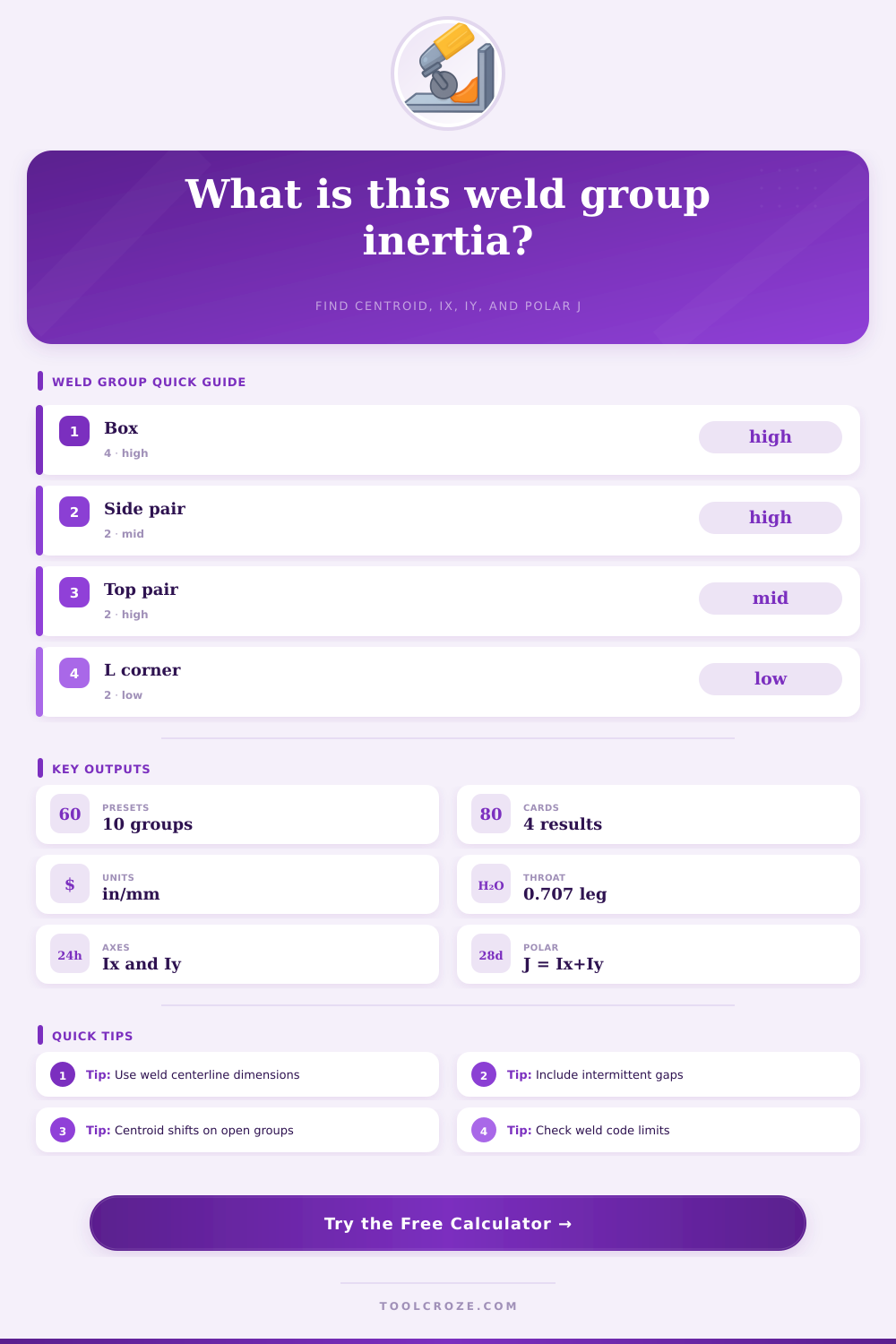
Choose a common weld layout. Each preset fills the weld centerline dimensions, throat settings, stitch pattern, and target eccentricity.
| Layout | Line model | Centroid behavior | Common use |
|---|---|---|---|
| Closed rectangle | Top, bottom, left, and right full lines | Centered when dimensions are balanced | Base plates, end plates, tube caps |
| Side pair | Two vertical lines separated by width | Centered between the lines | Brackets loaded about the weak axis |
| C shape | One vertical line plus top and bottom lines | Shifts toward the long vertical weld | Channels, open clips, access-limited plates |
| Stitch pair | Multiple short segments on each side | Depends on stitch count and spacing | Intermittent weld groups and long rails |
| Equal leg fillet | Effective throat | Area per inch | Area per 25 mm |
|---|---|---|---|
| 1/8 in or 3 mm | 0.088 in or 2.1 mm | 0.088 in2 | 53 mm2 |
| 3/16 in or 5 mm | 0.133 in or 3.5 mm | 0.133 in2 | 88 mm2 |
| 1/4 in or 6 mm | 0.177 in or 4.2 mm | 0.177 in2 | 106 mm2 |
| 5/16 in or 8 mm | 0.221 in or 5.7 mm | 0.221 in2 | 142 mm2 |
| Output | Formula basis | Use it for | Watch point |
|---|---|---|---|
| Centroid x, y | Sum of throat area times line midpoint | Locating the elastic weld group center | Open layouts can shift strongly |
| Ix | Integral of y squared over throat area | Bending or shear distribution about X axis | Vertical spread increases Ix |
| Iy | Integral of x squared over throat area | Bending or shear distribution about Y axis | Horizontal spread increases Iy |
| J polar | Ix plus Iy about the centroid | Torsion distribution from eccentric loads | Not a substitute for code design |
| Pattern | Calculator input | Geometry effect | Engineering check |
|---|---|---|---|
| Continuous perimeter | Layout width and height | Highest total length for the same envelope | Confirm weld access at corners |
| Balanced intermittent | Equal stitch count on both sides | Centroid stays near the middle | Check minimum length and spacing limits |
| Long side stitches | Increase stitch length before count | Raises throat area and local line inertia | Allow for starts, stops, and craters |
| Open corner group | L or C layout | Centroid moves toward welded legs | Check rotation and local prying |
Fillet welds is typically placed on the edges, corners, and seams of the metal plate, since those areas are usually not symmetric to the metal structure of that metal plate. Because of the lack of symmetry to the fillet welds, the loads that are applied to those weld groups does not always have a center point. In these instances, though, engineer must calculate the moment of inertia of those groups of fillet welds.
The moment of inertia will tell you the location of the center of that group of welds. Furthermore, the moment of inertia will also indicate how much that group of weld metal resist bending or twisting when loads are applied to those weld metal joints. In order to calculate the moment of inertia of each group of fillet welds, you must first determine the dimensions of each of the weld lines.
How to calculate the moment of inertia for fillet welds
Each weld line have a length, a throat thickness, and a position. The throat thickness is the distance across the weld metal of a fillet weld. For standard equal leg fillet welds, you calculate throat thickness as 70% of the size of the leg.
Once you know the throat thickness of each weld, you can treat the welds as thin strips of area. The total area of each strip is used as a denominator to calculate the centroid (or center) of the welded metal structure, and the distances from that centroid to each of the thin strips is the “lever arm” that is used to calculate the moment of inertia. The shape of the welded metal structure will play a role in the location of the centroid of that welded metal structure.
Metal structures that are “open” will have centroids located along the long vertical leg of those weld patterns. For instance, an open C-weld or an L-shaped welded bracket will have its centroid located along the vertical leg of the weld pattern. The widths, heights, and stitch pattern of the welded joint can be entered into a calculation to determine the offset of each weld pattern, and the centroid of the welded joint.
If the centroid of each of the welds in that joint is visible, engineers can compare the offset of those welds to the offset of the centroid of the welded metal structure to determine if the eccentricity of the load is balance or not. Joints that are closed have their centroids located at the center of that welded joint. If the joints are closed welded shapes, like a rectangle that is welded along its perimeter, the centroid will be located at the center of the welded rectangle.
The centroid located at the centre of the welded metal group will provide resistance to loads that act in either the x or y axis of that welded joint, indicated as Ix and Iy, respectively. If the welded metal forms a perimeter around a metal plate, access to the four sides of that metal plate will be required. Furthermore, access to the corners will also be required, since the last weld pass may otherwise exert a force on the metal plates that was welded prior to the last weld pass.
Intermittent welds, or “stitch” welds is welds that only partially go around a metal plate. Each of those stitch welds has a length, and the spacing between each of those welds will impact the resistance to bending and torsion that the metal joint will exhibit. If the stitch welds are too short or if they are too far apart from each other, the joint may not adequately resist loads.
Using an effective length factor in place of the actual length of the weld will account for the fact that the starts, stops, and crater fills along a joint will not contribute to the total strength of the welded metal joint. Reducing the effective length factor will reduce the values of each of the inertia calculations for that joint, which is a conservative means of calculating the actual strength of the weld. The polar moment of inertia (designated as the letter J) can be calculated by adding the values of Ix and Iy once each of those moments have been calculated about the centroid of the welded metal structure.
The polar moment of inertia is used when the load that acts upon a welded metal joint include torsion (or twisting) of the metal plate. Each weld segment that is farther away from the centroid will contribute more to the polar moment of inertia than weld segments that are closer to the centroid. For example, a base metal plate that is wide with fillet welds only along the outer edges will have a higher resistance to twisting than a narrow metal base plate with fillet welds along each of its outer edges.
The radius value of the polar moment of inertia will indicate how far the weld segment located at the outer edge of that metal base plate is from the center of that metal plate. Real welded metal joints will not always be as ideal as those represented by the calculated dimensions and lines. For example, the edges of the metal base plate may be beveled prior to welding, the root gap of the joint may not match the thickness of the metal base plate, and the throat of the welds may be smaller than the size of the leg of the fillet welds due to convex welds.
These features are not represented in the calculations of the moment of inertia of welded metal joints. Furthermore, each of these features will reduce the area of throat metal that can contribute to the moment of inertia calculations. Thus, the calculated moment of inertia is to be used as a starting point for stress calculations on those welded joints; the calculated value is not the final value for allowable load of those welded metal joints.
Joints can be compared to reference tables that indicate various weld patterns has different strength characteristics relative to the other weld patterns. For instance, a side-pair weld pattern is strong in one axis but weak in the other. Such a weld pattern is appropriate for those metal brackets if the load applied to that metal bracket will act along the strong axis of the joint, but would lead to failure if that force acts in the other axis of the joint.
Welding a perimeter around the metal plate will provide strength to each of the axes of the metal base plate. However, such a weld pattern will also increase the length of the welds and the heat input into the metal base plate. Excessive heat input may be undesirable in some metal base plate structures.
While it is possible to change the units from inches to millimeters during the process of calculating the moment of inertia of welded metal joints, the underlying math will be the same. Each of the throat sizes will be different, though, since those throat sizes are the size of the welds that will be created in the shop floor. Thus, the conversion of the units is mechanical, but the engineering decisions for the project are not a mechanical process.
For example, a six-millimeter leg size for a fillet weld may be the minimum leg size for that welded joint as required by code. Once the engineers have determined the moment of inertia of each of the welded metal groups, the engineers must make a decision. Based upon the calculations of the moment of inertia of each welded metal group, the engineers will determine what values of stress are created within each of the metal joints.
Each of those stress values can then be compared to the allowable stress values of the metal joints as required by code. Based upon that comparison, the engineers can decide what changes are necessary to the size of the leg of the fillet welds, the length of those welds, or the layout of the welds to provide adequate strength to the metal base plate. One of the most cost-effective changes may be to simply move one or more of the weld lines further from the centroid of the metal base plate.
Such a decision can be made in part due to the outcome of the calculation of the moment of inertia of the weld group prior to welding.