Effective Length Factor K Calculator
Estimate column effective length factor K from end restraint, sway or non-sway frame behavior, rotational stiffness ratios, unbraced length, section properties, and material strength.
📌Column Boundary Presets
⚙K Factor and Column Inputs
Effective Length and Buckling Results
🗂End-Condition Grid
📊Boundary Factor Reference
| End condition | Frame type | Typical K used here | Use when |
|---|---|---|---|
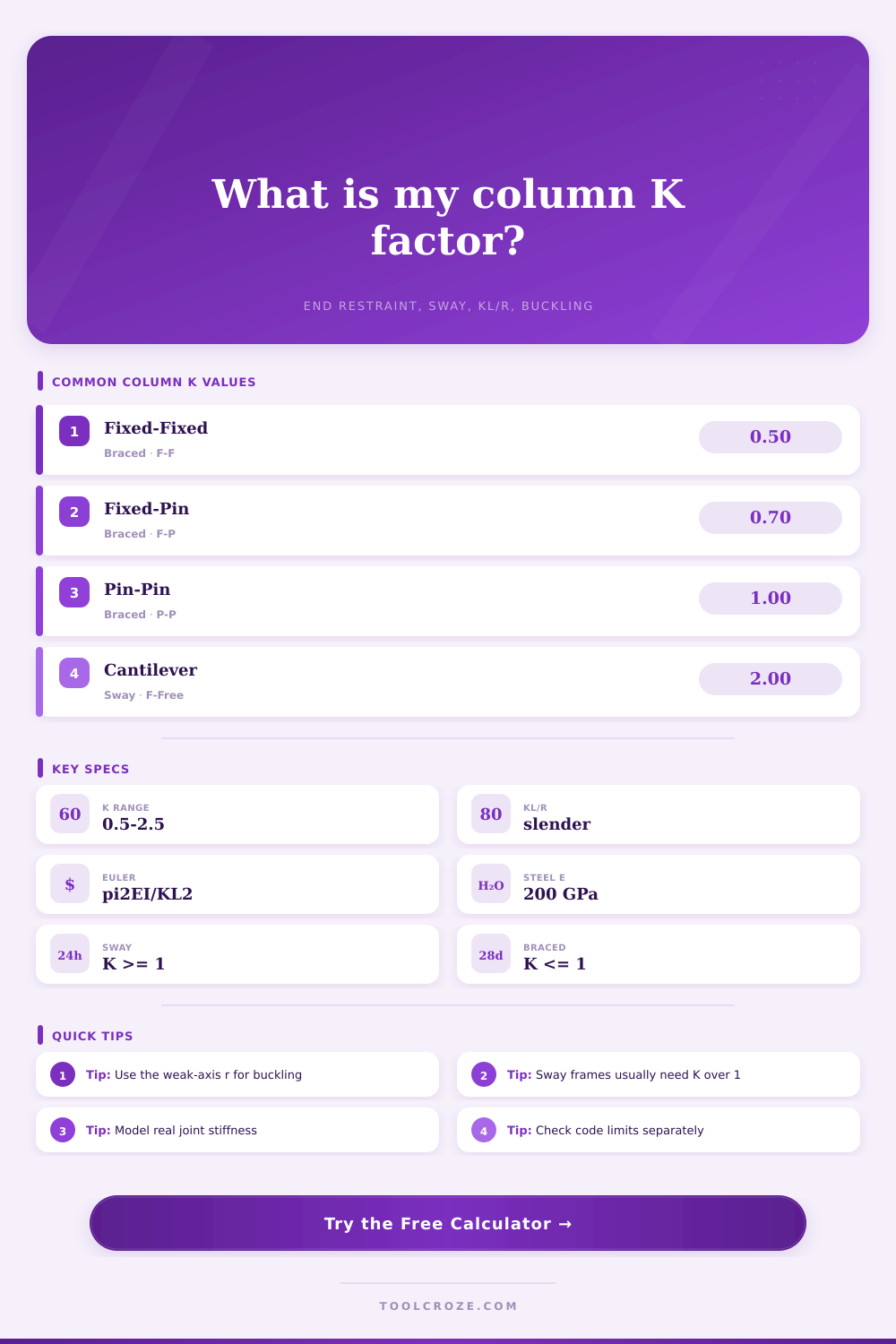
| Fixed at both ends | Braced / non-sway | 0.50 theoretical, often 0.65 design screen | Both joints restrain rotation and sidesway is prevented. |
| Fixed-pinned | Braced / non-sway | 0.70 theoretical, often 0.80 design screen | One end has meaningful fixity and the other is close to a pin. |
| Pinned at both ends | Braced / non-sway | 1.00 | Rotation is free at both ends while lateral translation is restrained. |
| Fixed-free cantilever | Sway / unbraced | 2.00 | Column behaves as a cantilever with an unsupported free end. |
| Fixed-fixed story column | Sway frame | 1.00 minimum | Moment frame allows sidesway but end rotations are restrained. |
| Semi-rigid story column | Sway frame | 1.2 to 2.5+ | Beam or base stiffness is not strong compared with column stiffness. |
🧱Material and Section Reference
| Material / section | Typical E | Common strength input | Section properties to use |
|---|---|---|---|
| Structural steel W-shape or HSS | 200 GPa / 29,000 ksi | Fy 250 to 450 MPa, 36 to 65 ksi | Use Ix or Iy and rx or ry from the steel table for the checked axis. |
| Aluminum column | 69 GPa / 10,000 ksi | Alloy yield strength from specification | Use the effective section properties for the governing buckling direction. |
| Glulam or timber post | 8 to 14 GPa / 1,200 to 2,000 ksi | Compression design value from wood code | Use actual net section area and least radius of gyration. |
| Reinforced concrete column | 20 to 35 GPa / 2,900 to 5,100 ksi | Concrete and steel interaction controls | Euler-only screening is not a substitute for moment magnification design. |
| Cold-formed steel stud | 200 GPa / 29,000 ksi | Fy from cold-formed section data | Local, distortional, and torsional buckling may control before Euler flexure. |
📐Slenderness and Buckling Interpretation
| KL/r range | Column behavior | What to check | Calculator signal |
|---|---|---|---|
| Below 50 | Stocky to moderately slender | Material crushing, local buckling, and code compression formulas. | Euler load is usually high compared with yield load. |
| 50 to 100 | Intermediate column | Inelastic buckling and member design curves. | Compare Euler, yield load, and actual axial demand. |
| 100 to 200 | Slender column | Second-order effects, frame stability, and end restraint assumptions. | K selection strongly affects capacity. |
| Above 200 | Very slender member | Temporary bracing, serviceability, and code slenderness limits. | Small load or length changes can dominate. |
📝Rotational Stiffness Ratio Guide
| GA or GB | Restraint meaning | Braced effect | Sway effect |
|---|---|---|---|
| 0 to 0.2 | Nearly fixed joint or base | K trends toward 0.5 when both ends are fixed. | K may remain near 1.0 if the frame sways. |
| 0.5 to 1.5 | Semi-rigid restraint | K usually falls between fixed-pinned and pinned-pinned cases. | K increases as beam or base restraint weakens. |
| 2 to 5 | Flexible joint restraint | K approaches the pinned braced limit. | K can exceed 1.5 in sway frames. |
| Above 5 | Very weak rotational restraint | Treat with caution; pinned may be optimistic. | Alignment chart or frame analysis is recommended. |
💡Calculation Tips
That means columns fail, but they don’t always fail dramatically, they fail expensively. They do not typically fail with a crack or a snap, as if someone surprised them by grabbing one end of a twig in winter and giving it a sharp yank. No, more commonly they bend, they buckle. They give up on the geometry long before actual material gives way.
And that’s where the effective length factor K come into play. K is the link between the real world column, the one that lives in your building, and the theoretical column that inhabits math. Get K wrong and everything downstream (the math of slenderness), capacity, and safety (are off). That’s where the calculator do the work for you, but knowing how it tweaks the numbers is what holds things up.
Understanding Column Stability and Safety Factors
Restraint is key idea here. If you hold one end of a column firmly in place and pin the other end, it will act different than if you embed that same column into a large concrete footing. For a fixed-fixed column, the theoretical K is 0.5. That reduces its effective length by half… Which increase the buckling load by four times. 5. That reduces its effective length by half… Which increases the buckling load by four times.
It’s a tiny alteration in the input resulting in a huge shift in the output. And most engineers is aware of that. Where things get dicey is in the real world, where no building can ever be perfectly fixed to a structure or perfectly pinned to another. Buildings exists somewhere in the messy middle.
Four bolts connecting a column to a steel beam isn’t a perfect pin; there’s some resistance provided making it semi-rigid. Modelling it as a pure pin could of been okay, but it also might be wasteful. Modelling it as a pure fixity, on the other hand, would be dangerous. How much rotation does that joint actualy provide? Estimate that.
That’s where the braced/sway thing realy matters. A braced frame has some form of diagonal brace or shear wall to keep it from swaying sideways, and the columns are primarily resisting gravity loads. But in a sway frame, they has to resist the same kind of lateral loading as wind and earthquake. That means nearly always a larger K factor. The table on the page makes that clear, with K jumping up to 2.0 or more if there is permission to allow sidesway. You can switch this behavior in the calculator which updates immediately with the change in buckling curve.
Just because something feels stiff doesn’t mean it’s braced. Specific lateral systems is required to be truly braced. If it’s taking lateral forces at the columns, then those columns is carrying the load… And that needs to be factored in.
The other big output is slenderness ratio. That’s the effective length divided by the radius of gyration. Simply stated, if the slenderness ratio is high (i.e., long and skinny compared to how strong it is) it’s governed by elastic buckling. If it’s low, meaning stocky, it’ll probably just get crushed instead of bending. The tool can give you the raw theoretical limit called the Euler load. Then it resist that with the resistance factor and screens that against your actual axial load. From there it gives you a usage percentage telling you how close you are to the edge. Get into the eighties and you’re in the danger zone. Small errors in K will prove fatal.
Theory is not reality. Textbook diagrams are not real-life construction. Connections gets loose. Foundations settles. Welds defect. That’s why design codes frequently recommend a little more K than required by theory. Theory suggest 0.5 for a fixed-fixed column. Practice commonly suggests 0.65. That’s a margin for imperfection.
And that’s what the calculator is for: it lets you input your own K, because maybe your site conditions require something else, or your connections are different. Override the defaults with whatever you think makes sense. Better to be a bit conservative in this case. Adding steel weight to a column is one thing; risking a collapse is another.
A safe building is only as good as its ability to stay standing; the difference between a collapsed building and a safe one is how much you trust the connection to hold. Trust them less; sleep better.