Drill Thrust Force Calculator
Estimate axial drilling load from drill diameter, material thrust coefficient, feed per revolution, point angle, pilot hole size, tool coating, coolant delivery, and peck mode.
Drill thrust force results
| Material | Specific thrust coefficient | Starting feed range | Typical point angle | Load note |
|---|---|---|---|---|
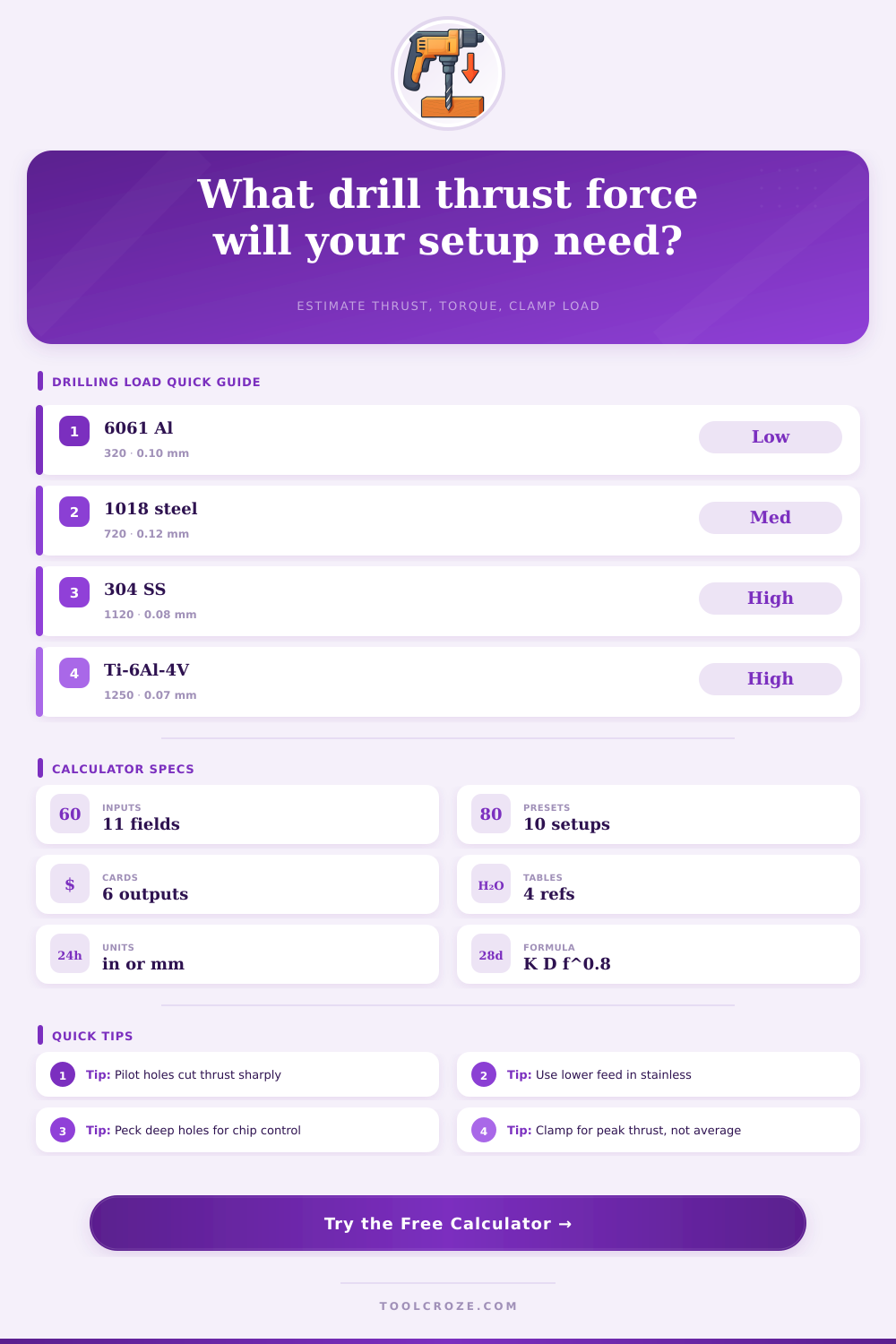
| Aluminum 6061-T6 | 320 N/mm/mmrev^0.8 | 0.08 to 0.18 mm/rev | 118 to 135 deg | Low thrust, manage chip weld |
| Brass 360 | 360 N/mm/mmrev^0.8 | 0.06 to 0.16 mm/rev | 118 deg or reduced rake | Free cutting, grabbing risk |
| Acrylic sheet | 260 N/mm/mmrev^0.8 | 0.04 to 0.10 mm/rev | 90 to 118 deg | Light feed to avoid cracking |
| Hard maple | 210 N/mm/mmrev^0.8 | 0.10 to 0.25 mm/rev | Brad point preferred | Low thrust, fiber breakout risk |
| Gray cast iron | 650 N/mm/mmrev^0.8 | 0.08 to 0.20 mm/rev | 118 to 135 deg | Abrasive, stable chips |
| Mild steel 1018 | 720 N/mm/mmrev^0.8 | 0.06 to 0.16 mm/rev | 118 to 135 deg | Medium thrust baseline |
| 4140 prehard steel | 950 N/mm/mmrev^0.8 | 0.04 to 0.12 mm/rev | 135 deg split point | High thrust and torque |
| Stainless 304 | 1120 N/mm/mmrev^0.8 | 0.03 to 0.10 mm/rev | 135 deg split point | High thrust, work hardens |
| D2 tool steel | 1180 N/mm/mmrev^0.8 | 0.03 to 0.09 mm/rev | 135 deg cobalt or carbide | Very high thrust |
| Titanium Ti-6Al-4V | 1250 N/mm/mmrev^0.8 | 0.025 to 0.08 mm/rev | 135 deg carbide | Severe heat and thrust |
| Input choice | Model factor | Primary effect | Best use | Check item |
|---|---|---|---|---|
| 118 deg standard point | 1.00 reference | Balanced thrust and centering | General HSS drilling | Web thickness and point wear |
| 135 deg split point | 0.92 to 0.96 | Less walking and chisel thrust | Steels and stainless | Needs adequate machine rigidity |
| TiN or TiCN coating | 0.95 to 0.98 | Lower friction at margins | Production holes in metal | Coating works only if edge is sharp |
| TiAlN carbide drill | 0.90 factor | Rigid hot-cutting setup | Alloy steel and titanium | Do not use on loose drill presses |
| Flood coolant | 0.93 factor | Reduces friction and chip welding | Aluminum and steel | Chip evacuation still matters |
| Through-tool coolant | 0.88 factor | Best chip evacuation in deep holes | CNC drilling over 5xD | Verify coolant pressure and flow |
| Pilot or peck condition | Typical factor | Thrust behavior | When to use | Setup caution |
|---|---|---|---|---|
| No pilot hole | 1.00 | Full chisel-edge thrust | Short holes in stable material | Center punch or spot if needed |
| 25 percent pilot diameter | 0.75 to 0.85 | Chisel load partly removed | Hand drilling larger holes | Pilot must stay straight |
| 50 percent pilot diameter | 0.52 to 0.65 | Large thrust reduction | Plate work and drill presses | Web may rub if pilot is too large |
| 75 percent pilot diameter | 0.35 to 0.45 | Low thrust, higher lip loading | Opening existing holes | Risk of grabbing at breakthrough |
| Standard peck cycle | 0.94 average | Lower packed-chip load | 3xD to 5xD holes | Peak thrust can still occur |
| Deep-hole peck cycle | 0.88 average | Better chip evacuation | Over 5xD holes | Use conservative feed and coolant |
| Preset | Material | Drill diameter | Feed per rev | Setup note |
|---|---|---|---|---|
| 1/4 in 6061 Jobber Drill | 6061 aluminum | 0.250 in | 0.0060 in/rev | Flood coolant, 118 deg point |
| 3/8 in 1018 HSS Twist Drill | Mild steel | 0.375 in | 0.0050 in/rev | Cutting oil, light peck |
| 5/16 in 304 Stainless Cobalt | 304 stainless | 0.3125 in | 0.0030 in/rev | 135 deg split point |
| 1/2 in Gray Iron Carbide | Gray cast iron | 0.500 in | 0.0070 in/rev | Dry or air blast |
| 6 mm Brass Split Point | Brass 360 | 6 mm | 0.10 mm/rev | Reduced grab setup |
| 8 mm Ti-6Al-4V Carbide | Titanium | 8 mm | 0.055 mm/rev | Through-tool coolant |
| 10 mm D2 Cobalt Drill | D2 tool steel | 10 mm | 0.060 mm/rev | Deep peck, cutting oil |
| 3/8 in Maple Brad Point | Hard maple | 0.375 in | 0.0100 in/rev | Brad point, no coolant |
| 1/2 in Steel With Pilot Hole | Mild steel | 0.500 in | 0.0060 in/rev | 0.250 in pilot hole |
| 8 mm Acrylic Low Feed Drill | Acrylic | 8 mm | 0.050 mm/rev | Low feed, light peck |
Thrust Force, When you drill holes, the drill thrust force can cause your drill press to walk across the bench. That’s axial load on the bit; how hard it push down on the workpiece. Does it break your bit? Do you get a nice clean hole? You’ll want to know those forces before you start, to set things right at the beginning. Then you can look at the forces using tool on this page.
Thrust is downward pressure of the drill bit as it cuts away material. That’s basically the chisel edge plowing material out of the way. Mostly it’s a diameter times feed to the 0.8 power times a material coefficient number. But the exponent make the difference. Thrust doesn’t increase in a straight line with feed. Double your feed and you typically get about seventy percent more thrust, not twice as much. Knowing the thrust vs. The feed curve help prevent overreaction when changing speeds and feeds.
How to Calculate Drill Thrust Force
And finally there is the material. Different materials makes all the difference. For instance, aluminum has low resistance and will forgive some chips. But if you get down to zero feed, it likes to weld itself to your tool. Mild steel is kind of a comfortable mid-range option for most shops. At the high end we have stainless and titanium which require sharper edges, slower feeds and often a split-point geometry. A split-point geometry keep the drill away from work-hardening the walls of the hole it drills. These numbers are what the charts on the page is referencing and they allow you to quickly see how each material compare. Titanium’s number is almost four times larger then aluminum’s. And that one number tell you why a drill of a given size will feel totally different in both materials.
Easy wins include drilling pilot holes and adjusting the point angle. A 135-degree split point (versus straight) reduces thrust by around five to eight percent with less chisel length, plus better centering. Even better are pilot holes. Cut away the center of hole until it’s halfway through or thereabouts. This reduces thrust to about half, as cutting becomes primarily a sideways task for the chisel. This is why they’re relieved; the chisel edge handles the bulk of axial action. The calculator takes that into account, automatically, allowing you to run tests without guesswork.
Peck cycles, coating, and coolant are secondary, but still has an effect after you get beyond 3 diameters out. Beyond that, through-tool coolant doesn’t just cool. It also blasts chips from the flutes, preventing them from packing up and causing sudden spikes in the load. Similarly, each retraction during a peck cycle shatters the chip and removes it from hole. This reduces the average force on the tool and guards against corner damage to the drill itself. These options adjust for these factors to ensure the final thrust figure is based off actual shop conditions and not some theoretical lab value.
What really surprises folks is the torque and clamp force numbers. The torque number tell you if your spindle can keep spinning without It stalls out. Stalling out. The clamp force number are telling you if your vise or fixture can hold onto the part while your drill is pushing as hard as it can. That’s typically when drilling a through hole, and it’s right about breakthrough where the hole breaks free. Always design to the peak load with a little safety margin, not the average. Ten percent sounds like a good amount of allowance until you see the part fly off the vise because they was too confident in the steady state.
Depth-to-diameter ratio matter and so do the materials; treating everything alike will cause common mistakes. A 1/2-in. Drill bit in a piece of 4140 six times its diameter deep won’t behave like that same drill in a thin sheet of aluminum. The calculator folds depth, operation type, and peck mode together so the severity rating at the bottom give you an honest traffic-light signal.
You can’t take experience away with this, but getting the numbers correct eliminates the guessing on those forces you’ll never feel until it’s too late. The few seconds it takes to run the numbers pays off. You will see that your drill bits is cutting cleaner. The part won’t move around as much. You will also spend less time chasing broken tool bit. That quiet confidence is worth it.