🔩 Drill Bit Converter
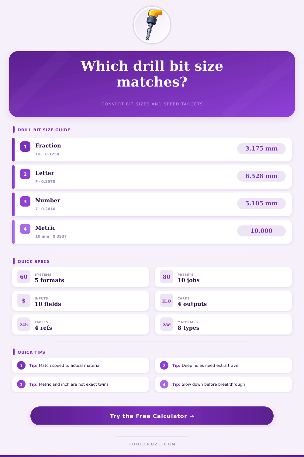
Convert drill sizes across fraction, decimal, letter, number, and metric systems, then check material-based RPM, feed rate, and drilling time in one workshop calculator.
📌 Presets
⚙ Converter Inputs
🎯 Results
📊 Material and Spec Grid
📑 Fraction to Decimal and Metric
| Fraction | Decimal in | Metric mm | Typical use |
|---|---|---|---|
| 1/16 | 0.0625 | 1.588 | Small pilot holes |
| 1/8 | 0.1250 | 3.175 | Hardware clearance pilots |
| 3/16 | 0.1875 | 4.763 | General shop drilling |
| 1/4 | 0.2500 | 6.350 | Bolts and dowel prep |
| 5/16 | 0.3125 | 7.938 | Medium bolt clearance |
| 3/8 | 0.3750 | 9.525 | Anchor and fixture holes |
| 1/2 | 0.5000 | 12.700 | Large pass-through holes |
| 3/4 | 0.7500 | 19.050 | Spade and hole saw pilots |
📘 Letter Drill Conversion Table
| Letter | Decimal in | Metric mm | Common role |
|---|---|---|---|
| A | 0.2340 | 5.944 | Close machine screws |
| C | 0.2420 | 6.147 | Pilot enlargement |
| F | 0.2570 | 6.528 | 1/4-20 tap drill |
| H | 0.2660 | 6.756 | Loose hardware fit |
| J | 0.2770 | 7.036 | Stud clearance work |
| N | 0.3020 | 7.671 | Larger tap prep |
| Q | 0.3320 | 8.433 | Fixture plate drilling |
| X | 0.3970 | 10.084 | Large imperial closeouts |
🔢 Number Drill and Tap Reference
| Number | Decimal in | Metric mm | Common use |
|---|---|---|---|
| 30 | 0.1285 | 3.264 | Rivet and electronics pilots |
| 21 | 0.1590 | 4.039 | 10-32 tap drill |
| 16 | 0.1770 | 4.496 | Sheet-metal prep |
| 7 | 0.2010 | 5.105 | 1/4-20 body hole pilots |
| 3 | 0.2130 | 5.410 | Close bolt clearance |
| 1 | 0.2280 | 5.791 | Larger screw prep |
| F tap pair | 0.2570 | 6.528 | 1/4-20 UNC tapping |
| Q tap pair | 0.3320 | 8.433 | 3/8-16 UNC tapping |
🛠 Material Speed and Style Comparison
| Material | Baseline SFM | Chip load per flute | Preferred styles |
|---|---|---|---|
| Softwood | 300 | 0.0035 in | Brad point, spade |
| Hardwood | 180 | 0.0028 in | Brad point, HSS |
| Plywood | 220 | 0.0025 in | Brad point, spade |
| MDF | 170 | 0.0022 in | Brad point, carbide |
| Acrylic | 90 | 0.0018 in | HSS, carbide |
| Aluminum 6061 | 250 | 0.0025 in | HSS, carbide |
| Mild steel | 80 | 0.0015 in | HSS, cobalt |
| 304 stainless | 50 | 0.0010 in | Cobalt, carbide |
💡 Tips
This drill bit converter matches size systems and applies shop-ready drilling formulas, helping you compare equivalents, speed, feed, and time before moving to the drill press or CNC program.
Drill bit size conversion is the process of changing a measurement from one system to another system. For instance, you might have to change a measurement from the imperial system to a metric system. You must perform drill bit size conversion because drill bits is manufactured in different systems of measurements.
Additionally, if you use the wrong size drill bit, the tap might be sloppy or the drill bit might snap on the workpiece during use. Drill bit size conversion require precision because the size of the drill bit determines the accuracy of the hole that is cut into the workpiece. Drill bits comes in various measurement scales.
Drill Bit Sizes and Safe Drilling
For example, fraction are used for many types of drill bits. Common drill bits use fractions in increments of 1/64 of an inch. Then, there are numbered drill bits that exist in the gaps between fractional drill bits.
Lettered drill bits fill the gap between small numbered drill bits and larger fractional drill bits. Metric drill bits use different measurements in millimeters. Additionally, metric drill bits do not always have the same measurements as imperial drill bits.
For instance, a drill bit that measure 10 millimeters is 0.3937 inches in diameter. However, a 10 millimeter drill bit will lie between the 3/8 inch drill bit and the 25/64 inch drill bit. It is important for drill bit size conversions to understand the difference between each of these systems because using the wrong size drill bit will lead to the creation of a hole that does not meet the tolerances that was required of that specific workpiece.
The hardness of the material that is being drilled will affect the type of drill bit that must be used. Additionally, the density of that material will affect the drill bit. The hardness of the material will determine the surface feet per minute (SFM) that is used with that type of material.
For instance, if the material is stainless steel, using a high SFM will create too much heat that might damage the drill bit. Using a low SFM with softwood will create an inefficient drilling process. The style of the drill bit will also affect the way in which the bit is used.
For instance, cobalt split point drill bits have a 135-degree angle, and they tend to self center in metal workpieces more better than standard high-speed steel (HSS) drill bits. Because the cobalt split point drill bit self-centers better, it can take higher RPMs when drilling into metal workpieces. Drill bit feed rate is the speed at which the drill bit move into the workpiece.
Feed rate is one of the most critical measurements in the drilling process. To calculate the feed rate, you multiply the RPM of the drill bit by the number of flutes on the drill bit and the chip load per tooth. For aluminum workpieces, the chip load must be set to a specific rate to keep the aluminum workpiece from becoming too hot during the drilling process.
For steel workpieces, the chip load will be smaller because the metal are harder. If you use a feed rate that is too aggressive for the material and drill bit you are using, the drill bit will dull due to the heat that will build up. On the other hand, if you use a feed rate that is too slow for the drill bit and material, the drill bit will rub against the material instead of cut it.
This rubbing can cause work hardening in stainless steel. A good way to make the drilling process more practical is to use presets. Presets allow the user to set the system to a specific drill bit and material.
Using this setting, the system can calculate the RPM and feed rate that should be used for this drill bit in this type of material. For instance, if a 3/16 inch HSS drill bit is loaded into a system that knows that it will be drilling into an aluminum plate, the system will calculate the proper feed rate and RPM for the drill bit. Using this function allows the user to reduce the chances of mistake and to make sure that the settings are safe for the bit.
Safety sliders can also be used to further reduce the RPM and feed rate for situations like handheld drills or inexperienced drillers. Some of the most common mistakes when drilling include ignoring the relationship between the diameter of the drill bit and the RPM of the drill bit. The larger of the drill bits diameter will require lower RPMs.
For instance, a drill bit that is 1/2 inch in diameter will require lower RPMs when drilling into steel than a drill bit that is 1/4 inch in diameter. Another of the most common mistakes is not considering the depth of the hole that will be drilled. For deep holes, peck cycles will be needed.
A peck cycle ensures that chips are cleared out of deep holes by moving the drill bit in and out of the material. For through holes, the travel distance of the drill bit will need to be adjusted so that it allows for the bit to breakout of the material. Different types of drill bits is meant to be used in different materials.
Carbide stub drill bits are used in materials like aluminum because these drill bits can handle high RPMs. Masonry bits are used to drill into concrete because the carbide tips on these bits can withstand the shock that is created when drilling into concrete. Spade bits are used in wood like plywood.
The reason that a spade bit is used in wood is because it can shear the wood rather than spiral the chips that are removed from the wood. A drill bit should be matched to the material to avoid vibration in the drill bit. Finally, two additional ways to improve the drilling process are to use coolant and peck cycles.
Coolant helps to control the temperature of the drill bit and the material. Peck cycles are used for deep holes so that chips are removed from those deep holes. An essential part of drilling is listening to the sound that is made by the cutting of the material.
A steady hum indicates that the drill bit is correctly cutting the material. However, a screech in the bit indicates that the RPM of the drill bit should be decreased. After drilling, the drill bit’s hole should be measured to ensure the size of the hole is as required.
Using the drill bit size conversion and correctly calculating the information for drilling will ensure that holes are clean and no mistakes are made with the drilling of the material. You’ll find that if you dont take care, the hole might be a mess. Its alot of work to get it right, but it’s worth it.
Actually, you should of checked the bit size first. The moddern drills can be tricky if you dont know your stuff.