Disk Spring Calculator
Estimate disk spring force, spring rate, stack travel, and stress from washer geometry, material, deflection, and single, parallel, or series stack layout.
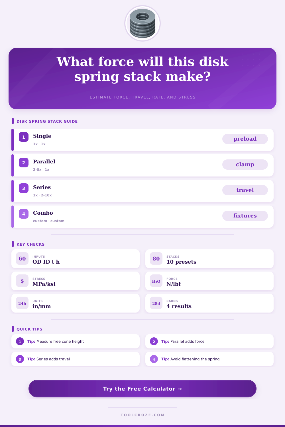
Choose a starting point, then fine tune the washer geometry and stack counts.
Calculation Breakdown
| Arrangement | Force Effect | Travel Effect | Common Use |
|---|---|---|---|
| Single disk | Baseline force | Baseline travel | Simple preload washer |
| Two parallel | About 2x force | About 1x travel | Higher clamp in small height |
| Four series | About 1x force | About 4x travel | Thermal growth take-up |
| Two by three combo | About 2x force | About 3x travel | Fixture and actuator stacks |
| Check | Preferred Range | What It Means | Warning Sign |
|---|---|---|---|
| OD / ID ratio | 1.6 to 2.5 | Stable washer geometry | Very narrow annulus |
| h0 / t ratio | 0.4 to 1.3 | Usable cone height | Over-high cone stress |
| Deflection / h0 | 15% to 75% | Working travel zone | Near-flat operation |
| Stack guidance | Use guide pin | Keeps disks aligned | Side loading marks |
| Material | Elastic Modulus | Static Limit | Typical Note |
|---|---|---|---|
| 51CrV4 spring steel | 206 GPa | 1500 MPa | High force general use |
| 301/302 stainless | 193 GPa | 1100 MPa | Corrosion resistant stacks |
| Inconel 718 | 200 GPa | 1350 MPa | Heat and corrosion service |
| Beryllium copper | 131 GPa | 760 MPa | Electrical contact springs |
| Use Case | Target Travel | Stack Preference | Design Check |
|---|---|---|---|
| Bolt preload | 20% to 50% h0 | Single or parallel | Clamp load repeatability |
| Vibration take-up | 30% to 65% h0 | Series groups | Travel reserve |
| Tooling clamp | 40% to 70% h0 | Parallel groups | Guide pin clearance |
| Fatigue service | 15% to 50% h0 | Lower stress stack | Stress range below limit |
Disk springs solve a problem by providing a way of providing high force from a component that take up little space. Disk springs dont require the same height as a coil or leaf spring to provide the same force. Furthermore, disk springs is shaped like a washer, but with a slight cone shape.
By compressing the disk spring until it is flat, the disk spring store energy. Because the disk spring stores that much energy within such a small height, they has a compact profile. Because of this compact profile, disk springs are often used in applications like valve, clutches, bearing preloads, and bolted joints.
Disk Springs: What They Do and How to Design and Use Them
The shape and material of the disk spring are created according to specific inputs. One of these specific inputs is the outside diameter of the disk spring. The inside diameter of the disk spring will determine the size of the bolt that will go through it.
The thickness of the disk spring will control the stiffness of the spring; altering the thickness will alter the force of the spring. The cone height will be the height of the spring when it is not compressed; it will impact the total travel of the disk spring. Finally, the material of the disk spring will impact its stiffness and stress limit.
Steel will provide high force and fatigue life with the spring, but stainless steels or nickel alloys will allow for high resistance to the temperature and corrosion that the spring may experience. Each of these values can be entered into the calculator to save the user from having to manually calculating each of these values. The arrangement of the disk spring stack is another critical element in the design process.
Using a single disk spring will provide a certain amount of force to the component and a certain amount of travel for that component. If additional disk springs are nested within the same direction as the first disk spring, the force will be multiplied while maintaining the same height of the spring stack. If disk springs are added in an opposed configuration, the travel of the disk springs will be multiplied without increasing the force of the system.
A combination of both of these arrangements can be used to increase the force and travel of the disk spring. The choice of which disk spring arrangements to utilize will depend upon the requirements of the mechanical joint. If vibration in the joint is a problem, for instance, series disk spring stacks will be utilized to allow for the joint to travel more.
However, if the bearing that is being utilized is exposed to varying loads, a parallel stack of disk springs will be used to increase the force without increasing the size of the bearing. Friction within the system created by the lubrication of the disk springs will introduce a drag into the system that alter the force of the disk spring arrangement. Another way that the designer can ensure that the disk spring will not fail during its use is by calculating the stress and deflection percentages of the disk spring.
The stress percentage will allow the designer to ensure that the stress of the disk spring is not too close to the stress limit of the material of the disk spring; too close to the stress limit will reduce the fatigue life of the disk spring. The deflection percentage will ensure that the system will not travel to the flattening point of the disk spring; going to that flattening point may lead to failures of the disk spring. Additionally, staying away from the flattening point will provide room for manufacturing errors in the system.
These percentages are created through the use of reference tables for disk spring designs. Many people make mistakes in there design of disk spring systems. For instance, some people select a disk spring based off solely upon its outside diameter; however, its force will be incorrect once it is assembled.
Additionally, some people will flatten the disk spring to its complete flattening; however, the force provided by the disk spring will drop off quick if the disk spring is flattened completely, which may cause the components of the system to chatter against one another. Furthermore, some people may use loose guide pins for the disk springs; however, tight guide pins will create friction within the system that alters the rate of the disk spring. Each of these mistakes are caused by the installation of the disk spring system, and are details that are invisible to the disk spring calculator.
The geometry of the disk spring should also be checked to ensure that it will function as intended. For instance, if the outside diameter of the disk spring to the inside diameter is too small, there is not enough diameter for the cone of the disk spring to form. Additionally, if the cone height of the disk spring is too tall in comparison to the thickness of the disk spring, the stress of the disk spring will not be distributed as the calculations suggest.
In these instances, the manufacturer data or finite element analyses of the disk spring design should be reviewed. One tool that the disk spring designer can utilize is the disk spring calculator. Such a calculator can be used to determine the force, the travel, the stress, and the deflection of the disk spring when of different materials, of different thicknesses, and with different force arrangements within the system.
Furthermore, once the designer chooses the disk spring geometry, samples of those disk springs should be ordered. These samples should then be measured; the dimensions of the batch of disk springs may not be the same as the calculations of the manufacturer. These calculations provide a target for the designer, but they are not a guarantee that the disk springs will be manufactured in such a way.
In using the calculator, the designer is forced to consider the disk spring as a system rather than a component. Each of the forces, travel, stress, and deflection are connected; altering one will alter the others, which may not be immediately obvious to the designer. People often do not consider these connections when they refer to the specification of the disk spring manufacturer.