Cylinder Retraction Force Calculator
Estimate hydraulic or pneumatic pull force from bore, rod diameter, pressure, efficiency, seal friction, mounting angle, load, and safety factor.
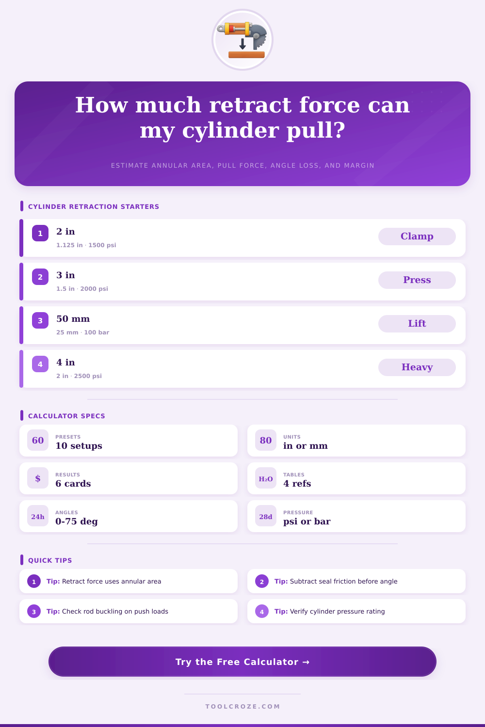
Pick a common air or hydraulic cylinder starting point, then tune the exact dimensions, pressure, load, and angle for the machine.
Calculation breakdown
| Cylinder size | Typical rod | Annular area | Retract force at pressure | Common use |
|---|---|---|---|---|
| 1.5 in bore pneumatic | 0.625 in rod | 1.46 in² | 131 lbf at 100 psi before losses | Light clamp, gate, small slide |
| 2 in bore hydraulic | 1.125 in rod | 2.15 in² | 3,220 lbf at 1500 psi before losses | Shop fixture, compact puller |
| 2.5 in bore hydraulic | 1.25 in rod | 3.68 in² | 5,520 lbf at 1500 psi before losses | Loader link, small press return |
| 3 in bore hydraulic | 1.5 in rod | 5.30 in² | 10,603 lbf at 2000 psi before losses | Press return, die lift, clamp beam |
| 4 in bore hydraulic | 2 in rod | 9.42 in² | 23,562 lbf at 2500 psi before losses | Heavy clamp, dump hoist, pull arm |
| 80 mm bore hydraulic | 45 mm rod | 34.4 cm² | 34.4 kN at 100 bar before losses | Metric machine cylinder |
| Medium | Usual working pressure | Efficiency guide | Friction allowance | Calculator note |
|---|---|---|---|---|
| Pneumatic shop air | 80 to 120 psi / 5.5 to 8.3 bar | 80% to 90% | 5% to 15% of theoretical | Use regulator pressure at the valve or cylinder port. |
| Low-friction pneumatic | 60 to 100 psi / 4.1 to 6.9 bar | 88% to 95% | Lower seal drag, cleaner motion | Common for guided slides and light automation. |
| Mobile hydraulic | 1500 to 3000 psi / 103 to 207 bar | 85% to 93% | Higher side load and seal drag | Pressure spikes do not replace continuous rating. |
| Industrial hydraulic | 1000 to 2500 psi / 69 to 172 bar | 88% to 95% | Depends on seals, guides, and oil temperature | Use measured pressure during retract if possible. |
| Cylinder angle | Useful force factor | Force lost sideways | Typical situation | Design response |
|---|---|---|---|---|
| 0 degrees | 1.00 x force | 0% | Inline pull, straight clamp | Best use of cylinder force. |
| 15 degrees | 0.97 x force | 3% | Minor bracket offset | Usually acceptable with margin. |
| 30 degrees | 0.87 x force | 13% | Common pivoted link | Check bearing side loads. |
| 45 degrees | 0.71 x force | 29% | Toggle or lift geometry | Upsize cylinder or revise linkage. |
| 60 degrees | 0.50 x force | 50% | Poor leverage near travel end | Expect high pin and guide loads. |
| Condition | Friction estimate | Safety factor | Best use | Watch item |
|---|---|---|---|---|
| Clean inline hydraulic cylinder | 5% to 10% of theoretical | 1.25 to 1.5 | Predictable fixture pull | Confirm pressure and seal condition. |
| Pneumatic cylinder with seals | 10% to 20% of theoretical | 1.5 to 2.0 | Automation and light clamps | Breakaway force may exceed running force. |
| Side-loaded or dirty service | 15% to 30% of theoretical | 2.0 to 3.0 | Outdoor equipment or rough linkage | Side load can damage rods and glands. |
| Vertical suspended load | Measure actual drag | 2.0 or higher | Lift, hoist assist, counterbalance | Use valves or mechanical support as needed. |
| Critical clamp or press return | Use tested force | 2.5 or higher | Personnel or tooling risk | Use engineered stops and rated components. |
This cylinder retraction force calculator computes theoretical force, efficiency losses, angle correction, annular pull area, safe load capacity and operational margin. When you pressurize the rod end, the piston retracts, which pulls on whatever is attached to it. Inside the barrel of the cylinder, there is space taken up by the rod.
That means theres less area that the piston can use. That reduces the output. By using this calculator, the calculator accounts for those variables in a systematic way.
How to Calculate Cylinder Retraction Force
Input your operating conditions, pressure values and cylinder dimensions and the calculator will give you back adjusted force numbers. No more estimating. It calculates them for you.
In this case, the full bore area is used for extension, while only the annular ring (between the rod and the bore) is used for retraction. In our example above, a one inch rod in a two inch bore cylinder will yield about two thirds of the extended pull when retracted. Simply adjust the rod diameter a little bit, and youve altered the available pull.
Because the cylinder doesnt create an equal amount of force in both directions, the designers will calculate separate retraction numbers. And the calculator will calculate the precise annular area from your entered dimensions and show the theoretical pull minus losses. The area calculation can be checked against the extension area as well.
Then you’ll tweak the rod size so that the pull is what you need. Finally, as the load begins to move, there is some friction that lowers the theoretical output. Resistance from each pivot pin, guide bushing and seal diminishes available power.
On average, a typical clean hydraulic system will lose only ten percent of its usable power to friction. If you are in a higher cycle application, or the environment is dirty, that percentage rises, allowing you to adjust it on the calculator. Efficiency rates all the resistance of the linkage, side loading and seal drag into one adjustment factor.
For clean service, you choose a ninety percent efficiency while choosing a seventy-five percent for heavier duty applications. The calculator then multiplies that number by the original number and shows the adjusted output. The pulling angle will also change the direction of the force and some amount of the pull is then diverted away from the load.
A 15 degree angle takes off a little less than a percent of effective power. About a 30 degree angle takes off about thirteen percent and a 45 degree angle puts nearly a third of its output in sideways stress. Using simple trigonometry you figure out the cosine of the angle and the calculator does the adjustment for you.
Without correction, worn out bushings and bent rods are all too common as the sideways stress is more than the design can handle, so take the time to measure what the real world geometry is prior to making the calculation. Your angle gets plugged in and the tool corrects the value which displays how much less pull it is that realy moves the load. Safety factors: They take into consideration component wear, pressure surges, variable loads, and the unknown operating conditions.
For a fixed application, a safety factor of 1.5 is enough to give us some margin. A lifting application needs more than this. To use the calculator, multiply your working load times the safety factor.
Next, compare that against the output of the corrected cylinder. If your cylinder doesnt meet the requirement, then the margin will be less than one. When the load outstrips the adjusted capacity, the cylinder fails in an overload situation.
Using the above comparison protects you from overload failure under normal operating conditions. Typical cylinder diameters fit into familiar force ratings. Small presses and shop fixtures run on a two inch bore at one thousand five hundred psi.
Large clamps and heavy hoists is supported by a four inch bore at two thousand five hundred psi. Air cylinders run between eighty and one hundred psi, with a greater portion of their power lost to friction. Charts of common pairings exist for reference tables so you can check if your application is in the normal range.
It’s always best to measure the actual pressure at the cylinder port when in operation since valve restrictions and line losses will drop the effective pressure. You’ll find that entry labeled “port pressure” on the calculator; this will yield a closer estimate of force than the pump gauge value. So when the rod extends it is a compressive force on the rod.
When it retracts it is tensile force on the rod. To get more out of retraction you want to increase rod diameter. And that bigger rod might decrease extension stability.
So all changes to dimensions effect both directions of travel. You have to consider the entire operating cycle. The calculator is only designed around retraction.
But you also need to check buckling resistance and extension force independently because most compression failure happen before the cylinder ever tries to retract. Again, you use the same rod and bore dimensions for extension calculation and then look at the results against your load requirement. That double check guarantees your cylinder operates properly in both directions.
But ultimately, its a substitute for guessing. It is still up to you to double check the operating environment, make sure the pressure reads are right, and check the physical geometry of the setup. The math gives you a starting point and then the operating conditions at the site is what tell if that starting point gets the job done or not.
You should of run the math prior to buying the cylinder, then tinker with the variables until the margin exceeds one. Running it correctly will keep failures from being a surprise and methodical inspections prolong component life. Follow the sequence of inputs, get consistent results with this tool.