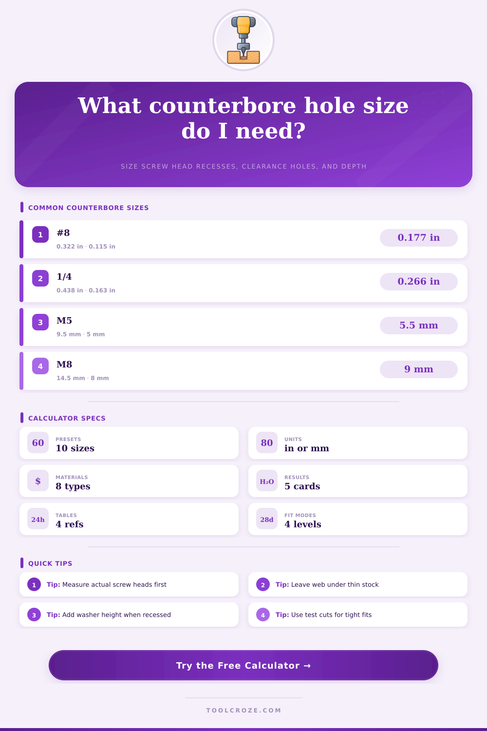
Counterbore Hole Calculator
Size a flat-bottom counterbore from screw head geometry, clearance hole, recess depth, washer allowance, material, and fit tolerance in imperial or metric units.
| Fastener | Nominal shank | Head diameter | Head height | Typical clearance |
|---|---|---|---|---|
| #6 flat or pan screw | 0.138 in / 3.51 mm | 0.279 in / 7.09 mm | 0.097 in / 2.46 mm | 0.149 in / 3.78 mm |
| #8 wood or machine screw | 0.164 in / 4.17 mm | 0.322 in / 8.18 mm | 0.115 in / 2.92 mm | 0.177 in / 4.50 mm |
| #10 wood or machine screw | 0.190 in / 4.83 mm | 0.373 in / 9.47 mm | 0.130 in / 3.30 mm | 0.201 in / 5.11 mm |
| 1/4 in socket head cap | 0.250 in / 6.35 mm | 0.438 in / 11.13 mm | 0.250 in / 6.35 mm | 0.266 in / 6.76 mm |
| 5/16 in socket head cap | 0.313 in / 7.94 mm | 0.531 in / 13.49 mm | 0.313 in / 7.94 mm | 0.328 in / 8.33 mm |
| 3/8 in socket head cap | 0.375 in / 9.53 mm | 0.625 in / 15.88 mm | 0.375 in / 9.53 mm | 0.391 in / 9.93 mm |
| M4 socket head cap | 4.0 mm / 0.157 in | 7.0 mm / 0.276 in | 4.0 mm / 0.157 in | 4.5 mm / 0.177 in |
| M5 socket head cap | 5.0 mm / 0.197 in | 8.5 mm / 0.335 in | 5.0 mm / 0.197 in | 5.5 mm / 0.217 in |
| M6 socket head cap | 6.0 mm / 0.236 in | 10.0 mm / 0.394 in | 6.0 mm / 0.236 in | 6.6 mm / 0.260 in |
| M8 socket head cap | 8.0 mm / 0.315 in | 13.0 mm / 0.512 in | 8.0 mm / 0.315 in | 9.0 mm / 0.354 in |
| Material | Minimum web | Bottom allowance | Counterbore behavior | Suggested tool |
|---|---|---|---|---|
| Softwood | 0.125 in / 3.2 mm | 0.006 in / 0.15 mm | Compresses easily; avoid over-tightening | Brad point or Forstner bit |
| Hardwood | 0.160 in / 4.0 mm | 0.010 in / 0.25 mm | Holds a crisp shoulder with sharp tooling | Forstner bit or piloted counterbore |
| Plywood | 0.180 in / 4.6 mm | 0.012 in / 0.30 mm | Face veneer can chip near the rim | Scored rim Forstner bit |
| MDF | 0.200 in / 5.1 mm | 0.012 in / 0.30 mm | Weak edges need a wider bearing area | Sharp Forstner bit with dust clearing |
| Acrylic or plastic | 0.180 in / 4.6 mm | 0.016 in / 0.40 mm | Needs light pressure to avoid cracking | Plastic drill or single-flute cutter |
| Aluminum | 0.120 in / 3.0 mm | 0.004 in / 0.10 mm | Clean bottom with rigid setup and lubricant | Counterbore, end mill, or piloted cutter |
| Mild steel | 0.100 in / 2.5 mm | 0.002 in / 0.05 mm | Watch heat and tool deflection | HSS or carbide counterbore |
| Stainless steel | 0.120 in / 3.0 mm | 0.002 in / 0.05 mm | Work hardens if rubbed or fed too lightly | Rigid carbide or cobalt tooling |
| Fit mode or washer | Add to diameter | Add to depth | Best use | Watch item |
|---|---|---|---|---|
| Tight shop fit | 0.004 in / 0.10 mm | material bottom allowance | Visible hardware in stable material | Test actual screw head first |
| Normal clearance | 0.010 in / 0.25 mm | material bottom allowance | General woodworking and fixtures | Finish thickness can reduce fit |
| Loose assembly | 0.020 in / 0.50 mm | material bottom allowance | Shop jigs and replaceable panels | Head may not look perfectly centered |
| Field drilled allowance | 0.031 in / 0.80 mm | material bottom allowance | Installations with hand drilling | Use washer if bearing area is small |
| Thin flat washer | diameter must fit washer OD | 0.031 in / 0.80 mm | Spreading load on wood or plastic | Counterbore must cover washer OD |
| Heavy washer | diameter must fit washer OD | 0.063 in / 1.60 mm | Fixtures and clamped metal parts | Depth can weaken thin stock |
| Tool type | Best materials | Typical finish | Depth control | Setup note |
|---|---|---|---|---|
| Piloted counterbore | Metal, plastic, hardwood | Very concentric | Stop collar or quill stop | Pilot must match clearance hole |
| Forstner bit | Wood, plywood, MDF | Clean rim, flat bottom | Drill press stop preferred | Clear chips in deep recesses |
| End mill | Metal, plastic, dense hardwood | Flat and accurate | Machine Z stop or DRO | Needs rigid workholding |
| Brad point drill | Softwood and hardwood | Good rim, conical center mark | Tape flag or stop collar | Works when center dimple is acceptable |
| Spade bit | Rough wood only | Rough bottom and rim | Depth stop required | Use only for non-visible work |
Counterboring is a process that is used to create a flat-bottomed pocket within a materials that will allow the head of a screw to sit flush with (or slightly below) the surface of that material. Counterboring allow the screw head to sit out of the way of the surface of the material, and prevents the screw head from protruding from the material. If the counterbore is too shallow relative to the screw head, the screw head will protrude from the material.
If the counterbore is too deep, however, the portion of the material that exists between the screw and the back of the part can be too thin for the screw’s shank and potentially break. Counterboring begins with measuring the specific fastener that will be used within that part. The published head diameter and head height of the fastener may differ from the actual dimension of the fastener.
How to Make a Flat Pocket for a Screw Head
Once you know the actual dimensions of the fastener, a decision must be made regarding how much extra room to provide for the fastener head. The amount of extra room required will depend upon the specific application of the part and the fastener. For instance, fixtures that require the fasteners to be repeatedly assembled may require more extra room to allow for movement of the fastener heads than visible joint created within hardwoods.
The depth of the counterbore is not simply the height of the screw head. If the fastener is to include a washer, the depth of the counterbore must also take into account the thickness of that washer. Additional material must remain within the part between the head of the screw and the back of the part to ensure that the shoulder of the screw does not crush the part.
The thickness of this remaining material is referred to as the web thickness of the part. The web thickness that is required within a part changes with the type of material that is being used. For instance, softwoods are more easily crushed than hardwoods, and thin materials such as plywood or MDF require more web thickness than hardwoods to prevent the face of the material from blowing out when the screw is tightened.
The diameter of the clearance hole that is provided underneath the counterbore is another variable in the counterboring process. The clearance hole must be large enough to allow the shank of the screw to fit within the part, but the clearance hole must not be so large that the screw head does not have a solid surface upon which to rest. You can drill the clearance hole before counterboring, but counterboring the hole first before drilling the clearance hole often provides more predictable results.
The difference in diameter between the shank of the screw and the clearance hole impacts the strength of the screw and the ease with which it can be inserted into the hole. The material from which the part is created impacts the counterboring process. For instance, aluminum and steel countersinks may require the use of sharp tools and lubricant to allow the screw to be inserted into the material.
Plastics, however, may crack if the screw is forced into the plastic. Additionally, the diameter of the counterbore may appear differently when a finish is applied to the part. For instance, a counterbore that appears correct for a piece of oak may reveal gaps between the screw head and the counterbore when the same counterbore is cut into cherry and a finish is applied to the cherry.
The tolerance settings on the counterbore tool can be adjusted to accommodate the potential difference in diameter between the screw and the counterbore. If a washer will be used within the assembly, the requirements of the counterbore will be different. For instance, the use of a washer will increase the depth of the counterbore, but the use of a washer may make the web thickness of thin materials dangerously thin.
Many counterboring mistake are made because people dont treat every screw the same. For instance, the head of a lag bolt is thicker than the head of a socket cap screw of the same size. Because the lag screw head is thicker, the depth of the counterbore is calculated differently for the lag screw than for the socket cap screw.
Another mistake is often made when people do not consider the thickness of the finish that will be applied to the part. For instance, if polyurethane or powder coat will be applied to the part, the screw may become a tight fit within the part. Therefore, if a finish will be applied to the part, the fastener head should of been selected as a loose-assembly head screw.
Finally, it is always recommended to perform a test hole within the material prior to applying the counterbore to the final material. A test hole can be performed within a sample piece of material that is of the same species (for wood) or alloy (for metal) as the material that is to be bored. A test hole allows the individuals to determine whether the bit will leave a flat enough bottom portion within the part for the screw head to sit flush with the part, and whether the chips will clear out of the bored portion.
Therefore, performing the test hole ensures that the hardware will seat within the part in the way that they calculated during the counterboring process. Its important to make sure you’re measurements are accurate to avoid any problems with teh final product. There is alot of room for error if you dont check the depth first.
One should of checked the hardness of the material too. The part sits on the table and the person use a drill to make teh hole. Making sure the hole is the right size is more important then getting the depth perfect, but you need both.
If the wood is too soft, the screw might loose its grip.