Concrete Thrust Block Calculator
Estimate pipe fitting thrust force, required soil bearing area, block face dimensions, concrete volume, and safety factor for bends, tees, reducers, valves, and dead ends.
Thrust Block Results
| Fitting | Coefficient K | Formula Basis | Common Use |
|---|---|---|---|
| 11.25° bend | 0.196 | 2 sin(angle / 2) | Small alignment change |
| 22.5° bend | 0.390 | 2 sin(angle / 2) | Offset around obstruction |
| 45° bend | 0.765 | 2 sin(angle / 2) | Major direction change |
| 90° bend | 1.414 | 2 sin(angle / 2) | Corner or tee approach |
| Dead end / valve | 1.000 | Pressure area only | Cap, plug, closed valve |
| Reducer | Area difference | P(A1 - A2) | Diameter transition |
| Nominal Pipe | Approx Area | Thrust at 150 psi | 90° Bend Thrust |
|---|---|---|---|
| 4 in | 12.6 in² | 1,885 lb | 2,665 lb |
| 6 in | 28.3 in² | 4,241 lb | 5,997 lb |
| 8 in | 50.3 in² | 7,540 lb | 10,663 lb |
| 10 in | 78.5 in² | 11,781 lb | 16,660 lb |
| 12 in | 113.1 in² | 16,965 lb | 23,992 lb |
| 16 in | 201.1 in² | 30,159 lb | 42,651 lb |
| Soil Type | Typical Bearing | Block Face Guidance | Field Check |
|---|---|---|---|
| Soft clay or silt | 750 to 1,000 psf | Large face, wider excavation | Avoid disturbed trench wall |
| Firm clay | 1,500 to 2,000 psf | Moderate block with clean face | Keep against native soil |
| Dense sand / gravel | 3,000 to 4,000 psf | Compact block footprint | Check trench stability |
| Shale or hardpan | 4,000 to 6,000 psf | Smallest typical face | Confirm no slick seams |
| Engineered backfill | Use geotech value | Match approved submittal | Document compaction |
| Scenario | Pipe / Fitting | Design Pressure | Starting Soil |
|---|---|---|---|
| Residential water bend | 6 in 90° bend | 200 psi | 2,000 psf |
| Street main offset | 8 in 45° bend | 200 psi | 3,000 psf |
| Distribution branch | 12 in tee | 210 psi | 3,500 psf |
| Fire main test | 8 in dead end | 250 psi | 2,500 psf |
| Large transmission bend | 16 in 22.5° bend | 190 psi | 4,000 psf |
When a water main pressurizes, the water inside wants to escape. If it encounters a dead end, a tee, or a bend, that pressure become a lateral force pushing against whatever is there. In our case, it’s trying to push the pipe out of the trench and push against fitting. This breaks joints and floods street.
A concrete thrust block prevents all that. It’s like a heavy shoe that take the push and moves it into surrounding soil. While the water are trying to move the pipe, the block holds it in place. This saves crews from having to dig up road to repair a blowout later.
Why You Need a Thrust Block Calculator
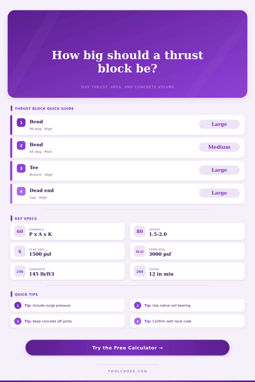
This is where the calculator comes into play. It does all the hard math on pressure conversion and some tricky trigonometry stuff too. Simply plug in the pipe size and its working pressure. Also select style of fitting, as it matters. Plug these in and it spits out how big of an area you need the soil bearing to be. That’s the size of the concrete face that needs to sit up against undisturbed earth. Too small and the block acts as a wedge, and the block just pushes its way through ground, making the whole thing worthless.
It also takes into account surge pressure. During hydrostatic testing, they push more pressure then normal operating levels. Thrust force directly relate to pressure. So a block rated for everyday might not survive first test. Allowing for surge protects the block from maximum stress.
The results depend a lot on soil conditions. Notice from the chart on that page that dense sand resists more than soft clay. Also, don’t pack loose backfill into the space behind the block. The block needs to bear directly on native soil. Ideally, this would of be soil that hasn’t been disturbed during the digging.
If the soil is wet or the trench walls have been ripped out, the bearing capacity decrease, and you’d need a bigger block face to compensate. Better to build the block just a bit too big rather than take any chance of it moving. By having a bigger face, you spread the force across a greater area. This decreases pressure per square foot on the soil.
Cutting corners on safety factors causes problems. Adjust the multiplier with the calculator. The higher, the bigger margin for error. If an area is high consequence (near a building foundation, under a busy road) then use a higher safety factor. Why? Because this will keep it from moving and causing joint separation.
Knowing how much concrete is required allows you to plan your pour. You will have enough material without any waste or lost money. Make it thick enough not to bend but not so thick it’s difficult to get into that tight trench.
Formulas are a guide, and field experience reveals what was missed in the formula. For instance, concrete should never be allowed to come into direct contact with bolts or other parts of pipe. Leave them exposed so they can be maintained as needed. Also, bad form work causes lopsided blocks. That doesn’t allow even bearing on surrounding soil. Make sure you have good compaction of the concrete behind the form so it makes good solid contact with the ground. Any air pockets becomes weak spots. And the soil will give way there first.
The simplicity of the solution hides the complicated physics that it addresses. Instead of using advanced material, we rely on simple workings of basic mechanics. The geometry has to be right and you have to abide by limitations of the soil. When the inputs are correct the block goes about doing its business without fanfare. After the crew departs, the block secures the line in position. This reliability is why the thrust block is so important to underground infrastructure.
Get the size right the first time; keep the system dry. Keep the system intact for decades.