Concrete Pier Load Calculator
Estimate round or square concrete pier capacity from pier size, concrete strength, rebar cage, soil bearing, axial load, lateral load allowance, slenderness, and safety factor.
⚙Real pier presets
📏Pier inputs
Concrete pier load results
🧱Reinforcement/spec grid
📊Soil bearing reference
| Soil description | Planning bearing | Drainage behavior | Use in calculator |
|---|---|---|---|
| Soft clay or loose fill | 1000-1500 psf | Poor to fair | Use conservative safety factor |
| Firm clay or silty sand | 1500-2500 psf | Fair | Common deck and porch planning |
| Medium dense sand | 2500-3500 psf | Good | Typical light structural piers |
| Dense sand and gravel | 3500-5000 psf | Good to excellent | Good capacity, still verify settlement |
| Weathered rock or engineered base | 5000+ psf | Excellent | Use geotechnical recommendation |
🔧Rebar cage reference
| Cage option | Steel area | Typical pier size | Calculator effect |
|---|---|---|---|
| Plain concrete | 0.00 in² | Noncritical short pier | No steel capacity added |
| 4 vertical #4 bars | 0.80 in² | 12-18 in round pier | Light ductility allowance |
| 4 vertical #5 bars | 1.24 in² | 16-24 in round pier | Moderate axial contribution |
| 6 vertical #5 bars | 1.86 in² | 20-30 in pier | Better confinement and capacity |
| 8 vertical #5 bars | 2.48 in² | 24-36 in pier | Heavy cage for larger piers |
| 6 vertical #6 bars | 2.64 in² | 30 in plus pier | High steel area warning check |
📝Concrete strength and pier behavior
| Concrete strength | Common use | Axial planning note | Field caution |
|---|---|---|---|
| 2500 psi | Light residential work | Lower margin for tall piers | Control water added on site |
| 3000 psi | General footings and piers | Common default for planning | Cure before full loading |
| 3500 psi | Exterior structural piers | Good everyday capacity | Use proper consolidation |
| 4000 psi | Columns and heavier loads | Higher axial reserve | Confirm mix and placement |
| 5000 psi | Engineered high-load pier | Often design-specific | Requires tighter quality control |
🏘Preset comparison table
| Preset | Geometry | Load | Best planning use |
|---|---|---|---|
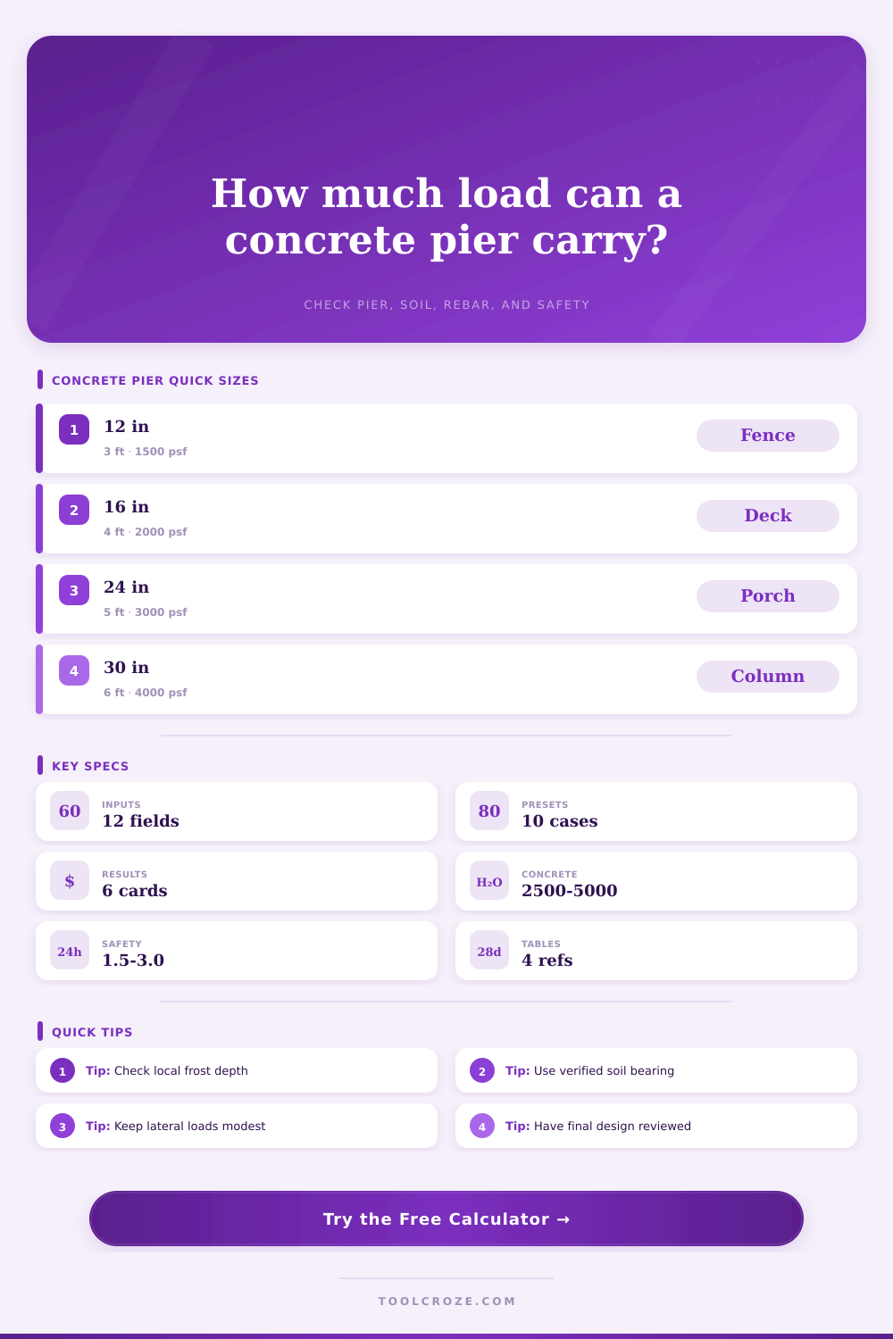
| 12 in Deck Pier | Round, 3.5 ft high | 4.5 kips | Small deck post reaction |
| 16 in Porch Pier | Round, 4 ft high | 8 kips | Porch beam or landing support |
| 18 in Pergola Pier | Round, 5 ft high | 6 kips | Light roof with wind allowance |
| 24 in Crawlspace Pier | Round, 5 ft high | 18 kips | Interior beam support |
| 30 in Grade Beam Pier | Round, 6 ft high | 32 kips | Heavier framed structure |
💡Calculation tips
A concrete pier is a block of cement. Wrong. A concrete pier is a compromise between a block of cement and the weight resting on it, and the ground beneath it. When the compromise doesn’t work, what happens? Cracks form! And eventually, the whole thing might collapse or at least settle.
The load-bearing calculations performed by the calculator (above) use soil conditions along with material strength to calculate capacity according to geometry. In other words, it removes guesswork about whether the foundation will support the load. That’s something you can depend on, assuming that your inputs is honest.
Why Concrete Piers Are Safe
Most people overlook the soil first. If the soil gives way, the whole structure will sink unevenly. The tool request allowable soil bearing pressure, in pounds per square foot. For soft clay, expect something on the order of fifteen-hundred psf or less; dense sand can bear more weight, sometimes up to four-thousand psf or beyond. Why does that matter? Because when the soil collapses, it do so suddenly and silently. The concrete doesn’t “crack” first; instead, the whole building slowly sinks until you notice it one day and are left with a expensive surprise. A trusted site value help avoid that.
Steel reinforcement and concrete strength also matters. For most porch support, standard residential mixes reach three thousand psi. You can change that in the calculator. And it considers the steel reinforcement cage. Without added steel, plain concrete isn’t very strong in tension; it cracks easily when pulled on. By adding vertical bars, like four number five rebar, you increase ductility to help pier withstand lateral shifting or wind bending moments. Different cage setups change safety margin (see reference table). That gives you a better idea of who’s holding up your weight.
Being slender makes one unstable because of their height. A stubby little pier is quite stable. It is not slender. When a pier gets long and skinny like a ruler standing straight up, it want to buckle. The calculator automaticly calculates this. If your pier is too narrow for its height, it will alert you.
This includes lateral load. This is the wind pressure against deck railing and the entire structure. It applies force trying to snap the pier in half at the bottom. Enter a reasonable amount of lateral force into the tool to calculate the moment allowance. This prevents it from snapping or bending out of shape under any kind of weight.
Reality doesn’t operate within bounds of theory; there are safety factors. Two zero and one point five are common numbers on the tool. The greater the number, the more conservative design. This provides more leeway to account for unexpected loads and variation in material quality. It is not because you’re paranoid, but because you’re prepared. Building projects get messy. Soil reports aren’t ever perfect, curing conditions vary, and the concrete mix might be slightly different than expected. Having some margin built into construction protects against weakening the structure with a little wetter weather or a different concrete mix.
You should of had a plan. The tool isn’t a permit; it’s a planning aid, a way to visualize the physics of your foundation before pouring concrete. Try out various diameter options. Compare different rebar configurations. See how soil types affects the equation.
When it comes time to break ground, local codes and frost depths will determine final specs. The calculator will help you understand the tradeoffs, get your numbers into the ballpark, and then leave it up to a professional engineer to sign off on the details. That way, when you step onto your new deck, you’ll be standing on solid ground, not on hope.