Compressor Air Storage Calculator
Size receiver reserve from tank volume, cut-in and cut-out pressure, tool demand, compressor delivery, leaks, altitude, and intake temperature.
▣ Storage Presets
⚙ Receiver, Pressure, and Demand
▦ Current Storage Snapshot
☰ Reference Tables
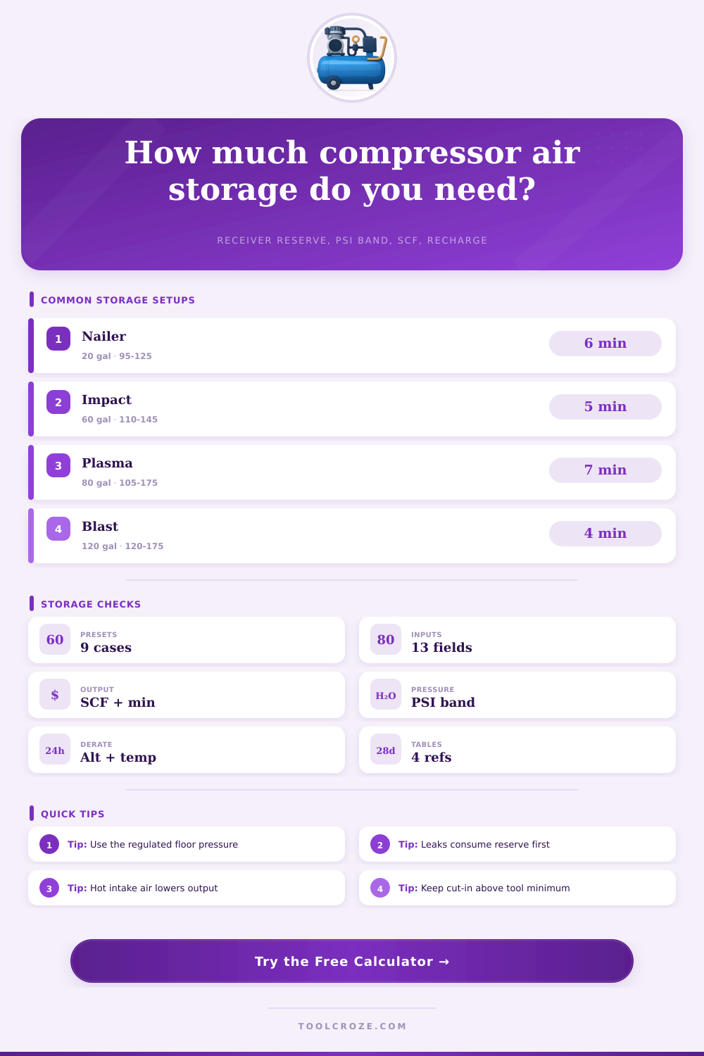
Receiver storage by pressure band
| Receiver | 90 to 120 PSIG | 110 to 145 PSIG | 120 to 175 PSIG | Best use case |
|---|---|---|---|---|
| 20 gallon portable vertical | 5.3 SCF usable | 6.2 SCF usable | 9.8 SCF usable | Trim nailers, tire top-off, small blow gun bursts |
| 60 gallon shop receiver | 16.0 SCF usable | 18.7 SCF usable | 29.4 SCF usable | Impact tools, grinder bursts, plasma with modest duty |
| 80 gallon upright receiver | 21.4 SCF usable | 24.9 SCF usable | 39.2 SCF usable | Plasma cutting, finish spraying, tire service |
| 120 gallon receiver bank | 32.1 SCF usable | 37.4 SCF usable | 58.8 SCF usable | Blast cabinets, two-person work cells, high surge loads |
Typical shop air demand for storage sizing
| Air use | Running SCFM | Common floor pressure | Storage behavior | Sizing note |
|---|---|---|---|---|
| 16 gauge finish nailer crew | 2 to 6 SCFM average | 85 to 100 PSIG | Short pulses with long idle gaps | Small tank works if compressor recovers between bursts |
| 1/2 inch impact wrench | 8 to 16 SCFM running | 90 to 110 PSIG | High bursts, moderate pauses | Receiver helps keep torque consistent during stubborn fasteners |
| Plasma cutter air supply | 5 to 9 SCFM continuous | 95 to 120 PSIG | Steady draw during arc-on time | Use dry storage and watch pressure sag at pierce |
| Blast cabinet gun | 15 to 30 SCFM running | 90 to 120 PSIG | Long continuous draw | Storage smooths dips but cannot replace compressor capacity |
| HVLP conversion gun | 9 to 15 SCFM running | 40 to 60 PSIG upstream | Steady passes with refill pauses | Size for pass length plus stable regulator inlet pressure |
Receiver, storage, and compressor comparison grid
| Configuration | Storage advantage | Compressor concern | Pressure control | Best match |
|---|---|---|---|---|
| Single small receiver | Fast recovery, compact footprint | Cycles often on bursty tools | Wide band may be noticeable | Portable trim, field repairs, light tire work |
| Large vertical receiver | More SCF per pressure band | Needs adequate pump to refill | Stable if regulator has enough inlet pressure | General shop, impact, die grinder, spray prep |
| Auxiliary drop tank | Adds local surge reserve at point of use | Long lines can slow recharge | Useful near high-flow stations | Remote bay, CNC blast nozzle, tire station |
| Receiver bank | High reserve without very wide pressure band | Can mask undersized compressor until pressure falls | Works best with check valves and drains | Blast cabinet, plasma table, shared shop header |
Altitude and intake temperature delivery correction
| Condition | Approximate factor | What changes | Storage effect | Practical response |
|---|---|---|---|---|
| Sea level, 68°F intake | 1.00 | Nameplate SCFM is closest | Normal recharge estimate | Use measured SCFM when available |
| 3,000 feet altitude | About 0.91 | Lower inlet air density | Receiver empties the same, refills slower | Add compressor capacity or reduce duty |
| 95°F compressor room | About 0.95 | Hot intake reduces mass flow | More runtime needed to recover | Ventilate intake area and avoid hot recirculation |
| 5,000 feet and 95°F | About 0.82 | Altitude and heat stack together | Reserve feels shorter during long draws | Use wider storage band or larger compressor delivery |
ℹ Practical Storage Notes
Air storage sizing determine how much air a compressor tank can provide to your tools. Eventually, the air tank will drop to the pressure that the regulator maintains. If the demand on the air tank is high enough, the air tank will empty more faster than the compressor can replenish the air tank.
This emptying of the air tank will cause a drop in the pressure that is provide to the tool. Air storage sizing intends to solve the problem of the difference between the air that is held within the tank and the air that is delivered to the tool. The amount of air that the receiver can provide to you is dependent on the spread of the air pressure that you use.
How to Size an Air Compressor Tank
The higher the cut-out pressure, the more air can be stored within the tank. However, raising the cut-out pressure also raises the stress on the tank, the relief valve, and the tool regulators. The lower limit of the air pressure is established as the pressure requirement of the highest requirement tool plus the air loss in the hose, the filter, and the regulator.
Any air pressure lower than this limit is not usable air for the tools, even though the pressure gauge may read that there is air in the tank. The calculator can do the mathematics for you once you have enter the two limits of air pressure, the volume of the tank, and the temperature at the intake of the compressor. Both the temperature and the altitude at which the compressor is located will alter the amount of mass that the compressor moves.
When the intake air is hotter, it is less dense than cooler air. Therefore, the same displacement of the compressor will move fewer standard cubic feet of air if the intake air is hotter. Altitude also plays the same role as heat in regard to air density.
The correction factor for temperature and altitude are not significant if the compressor is located at modest heights. However, at elevations of four thousand feet, such a correction factor will be significant. This derate factor accounts for the physical properties of air density but does not indicate a change in the air tank itself.
The demand for air from your tools is the most important consideration when sizing the air storage system within your shop. A tool such as a finish nailer may draw six standard cubic feet of air per minute for a period of two seconds before idling for twenty seconds. However, a tool like an impact wrench can draw fifteen or twenty standard cubic feet of air per minute for the same amount of time.
If the average amount of air that the tools draw from the tank is more than the air that the compressor can supply to the tank, then air storage will only provide you with a brief amount of time before the air pressure falls again to the level that the tools require. This margin result will show either if the compressor will be able to keep up with the demands of the tools after the burst of demand, or if air storage will be required to meet every sustained demand for air from those tools. Recharge time is another aspect to consider in the sizing of air storage.
A large receiver tank can store enough air to meet a burst of demand for your tools. However, if the compressor takes twelve minutes to refill the air tank after a burst of demand from the tools, it is possible that another burst of demand will occur before the tank is filled with air to the level required by the tools. This calculation will allow you to see if the compressor will have time to refill the tank during the pauses of tool use.
Many people rely upon a rule of thumb for sizing their air tanks. Other people copy the air storage system that one of their neighbors implemented. These methods of determining the size of air storage can fail if there are changes to the tools within the shop or if the demands for air from those tools increases.
A sixty gallon tank is often implemented within the shop that has a variety of tools because a sixty gallon tank provides an amount of usable air pressure without taking up too much space within the shop floor. However, such a tank can be insufficient for the needs of two people using grinders at the same time, or if the plasma table is in use. Adding an auxiliary receiver tank will allow tools closer to the air tank to receive a higher air pressure, but will have no effect upon the capacity of the compressor.
Thus, there is a decision to be made regarding increasing the air storage within the system, and another decision regarding increasing the capacity of the compressor to supply that air. Leaks in the air system will consume the air tank without providing any benefit to the tools. A slow leak in a coupler will not be registered by the tools as a demand for air, but it will reduce the number of minutes that the tools can run.
The allowance for leaks that is required of the user will be incorporated into the average draw of air from the tank to ensure accuracy in the estimate of the amount of time that the tools will run. The size of the air tank can be increased or the air compressor can have its capacity increased. Air storage and air compressor each has their benefits and limitations within the air system.
Increasing the amount of volume of the air tank will allow it to handle more bursts of demand from the tools, and will smooth the air pressure that is supplied to the regulator. However, extra air tanks will not fix problems created by the air compressor that is already running at or near its limit. Thus, the numbers that are entered into the air storage calculator will allow you to determine whether the air system that is to be built will be able to handle the demands of the tools within the shop when the shop is busy.