⚙ Compound Gear Ratio Calculator
Calculate total ratio, output RPM, and torque multiplier for 2–4 stage compound gear trains
High torque capacity
Most common choice
Good damping
Heavy machinery
Self-lubricating
Low noise
Corrosion resistant
Marine/food grade
| Driver \ Driven | 20T | 24T | 30T | 36T | 40T | 48T | 60T | 72T |
|---|
| Application | Stages | Typical Overall Ratio | Use Case |
|---|---|---|---|
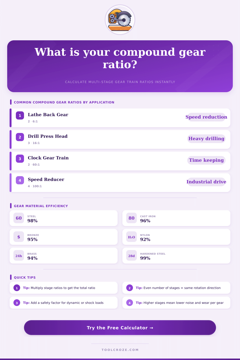
| Lathe Back Gear | 2 | 4:1 – 8:1 | Low-speed heavy turning |
| Gear Head Drill Press | 3 | 12:1 – 20:1 | Variable speed drilling |
| Clock Gear Train | 2 | 60:1 | Minute to hour hand |
| Conveyor Speed Reducer | 2 | 5:1 – 15:1 | Material handling |
| Printing Press Feed | 3 | 8:1 – 12:1 | Synchronized paper feed |
| Machine Tool Rapid | 2 | 3:1 – 6:1 | CNC rapid traverse |
| Industrial Speed Reducer | 4 | 50:1 – 150:1 | Heavy industrial drive |
| Bicycle Derailleur | 2 | 0.6:1 – 4.5:1 | Variable pedal ratio |
| Automotive Transmission | 3 | 2.5:1 – 4:1 | 1st gear ratio |
| Wind Turbine Gearbox | 3 | 50:1 – 100:1 | Rotor to generator |
| Input RPM | Ratio 2:1 | Ratio 4:1 | Ratio 8:1 | Ratio 16:1 | Ratio 32:1 | Ratio 60:1 |
|---|
When one puts several pairs of gears together on one same shaft one sees what one calls a compound gear chain. The advantage of that setup is that every pairs of gears sit together, forming what we call compound gear systems. What does it do, is that two gears are bound to one single shaft spinning at same speeds.
That is why engineers use that idea, to hand over power well through short distances, while one still reaches big changes in speed or torque.
How Compound Gear Chains Work
Here is why that matters. The reason is this: if you try to reach a big gear ratio by means of only one pair of gears, one of them should be really huge. Assume that you want to reduce from 2000 RPM to 500 RPM by means of one single pair, you would have a 20-tooth gear working with an 80-tooth giant.
Here is where the compound gear system changes everything. Instead of one huge wheel, one uses a series of smaller gears, that is much more easy to build and fit. Also, spreading the work through several stages allows the torqeu to grow slowly instead of putting all tension on one set of teeth.
Counting the ratio of a compound gear chain is not very hard. One finds what ratio each pair gives, then simply multiplies them together. Assume that your first stage gives 5:1 and the second stage is also 5:1.
Multiply those? You get 25:1 in whole. Or imagine a first ratio of 7:1 with second around 2.33:1, that results in around 16.33:1 overall.
A real sample helps understand that well. Assume that you have blue gears with 7 and 21 teeth on each side and green gears with 9 and 30 teeth. The first ratio comes from 7 against 21, while the second is 9 against 30.
Multiplying across, one gets 63 against 630, which simplifies too 1:10. That same multiplying of fractions counts everywhere. Have one pair at 1/3 and another at 1/7?
Multiply those fractions and you arrive at 1/21, like this your compound gear ratio becomes 1:21.
For a four-gear chain, the calculation works like this: one takes the number of teeth of the second gear divided by the first, then multiplies that by the number of teeth of the fourth gear divided by the third. Written, it is (gear 2 / gear 1) times (gear 4 / gear 3). If your whole gear ratio reaches 4:1, the last gear does one full turn for every four turns of the input.
Compound gear chains add also flexibility to the system. Different kinds of gears… Spur, helical, bevel.
Can work in one same setup, depending on what is most important: noise levels, load ability or how they are placed. Take the M… D. Ark as a sample from the real world.
A 36-tooth gear turning a 12-tooth one gives a stage ratio of 1:3 alone, but putting everything together, one turn of the entry makes the output twist more than three times. Here is the multiplied force thatmakes that whole method so useful.