Compound Angle Infeed Threading Calculator
Convert thread pitch, included angle, compound setting, dial infeed, radial depth, flank advance, finish allowance, spring passes, and tool geometry for single-point lathe threading.
Compound infeed results
| Pass | Radial depth | Compound dial | Pass increment | Cut role |
|---|---|---|---|---|
| Calculate to build the schedule. | ||||
| Thread form | Included angle | Common compound | Radial depth guide | Tool geometry note |
|---|---|---|---|---|
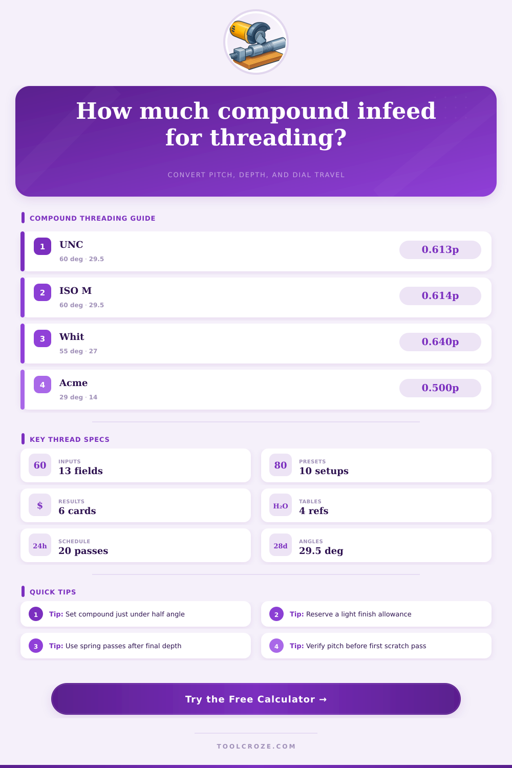
| Unified UNC / UNF external | 60 deg | 29 to 29.5 deg | 0.6134 x pitch | Flat crest and root, 60 deg tool |
| ISO metric external | 60 deg | 29 to 29.5 deg | 0.6134 x pitch | Use metric pitch and 60 deg insert |
| NPT pipe thread | 60 deg | 29 to 29.5 deg | 0.8000 x pitch guide | Taper and gauge engagement still govern |
| Whitworth / BSP | 55 deg | 26.5 to 27 deg | 0.6403 x pitch | Rounded root and crest profile |
| General Acme | 29 deg | 14 to 14.5 deg | 0.5000 x pitch plus clearance | Flat-topped tool with width control |
| Metric trapezoidal | 30 deg | 14.5 to 15 deg | 0.5000 x pitch plus clearance | Check tool width against standard |
| Material | Starting SFM | Pass style | Spring passes | Shop cue |
|---|---|---|---|---|
| Mild steel 1018 | 60 to 100 | Balanced reductions | 1 to 2 | Watch chip color and tearing |
| Alloy steel 4140 | 35 to 70 | Smaller late passes | 2 to 3 | Use rigid setup and sharp tool |
| 316 stainless | 20 to 45 | Firm non-rubbing cuts | 1 to 2 | Avoid dwell and work hardening |
| 6061 aluminum | 150 to 300 | Open chip, fast finish | 1 | Use polished or sharp geometry |
| Free machining brass | 120 to 250 | Light even cuts | 0 to 1 | Control chatter on fine pitch |
| Gray cast iron | 45 to 90 | Dry, shallow finish | 1 to 2 | Keep abrasive dust contained |
| Bearing bronze | 70 to 140 | Steady depth cuts | 1 to 2 | Use rake suited to the alloy |
| Acetal plastic | 180 to 350 | Sharp, low pressure | 0 to 1 | Leave room for spring and heat |
| Setup item | Formula or check | Why it matters | Adjustment cue |
|---|---|---|---|
| Compound dial travel | Radial depth / cos(angle) | Dial moves along compound, not straight in | Use actual compound scale convention |
| Flank side travel | Dial travel x sin(angle) | Shows how far the tool feeds along the flank | Too much side feed can rub back flank |
| 60 deg tool nose flat | 0.125 x pitch common | Prevents a fragile sharp V point | Stone or select insert to match thread form |
| Whitworth tool | 55 deg plus rounded tip | Angle and root form are not 60 deg | Use a Whitworth gauge to verify |
| Acme / trapezoid tool | Flat width from pitch standard | Width controls root clearance and fit | Check with wires or mating nut |
| Spring pass amount | 0 to 0.0005 in radial | Clears flex without overshooting size | Zero infeed if the thread is near gauge size |
| Preset | Pitch / TPI | Thread angle | Compound | Pass plan |
|---|---|---|---|---|
| 1/4-20 UNC Steel Stud | 20 TPI | 60 deg | 29.5 deg | 8 cuts + 2 spring |
| 1/2-13 UNC Mild Steel | 13 TPI | 60 deg | 29.5 deg | 10 cuts + 2 spring |
| 1/2-20 UNF 316 Stainless | 20 TPI | 60 deg | 29.0 deg | 11 cuts + 2 spring |
| M10 x 1.5 ISO Thread | 1.5 mm | 60 deg | 29.5 deg | 9 cuts + 2 spring |
| G1/4 BSPP Whitworth | 19 TPI | 55 deg | 27.0 deg | 10 cuts + 2 spring |
| 3/4-10 Acme Leadscrew | 10 TPI | 29 deg | 14.0 deg | 14 cuts + 3 spring |
This is for lathe threading. This handy calculator lets you input pitch, included angle, radial thread depth, compound dial travel, flank advance, pass schedule, and spring pass cleanup. It give you clean output for your machine.
Lathe threading seems easy until you are standing there staring at a piece of material in the chuck and you have to do the threading on the lathe. One wrong infeed and the tool dig into the workpiece. One wrong infeed and you tear the flank or worse yet ruin the part. The feed rate make the cutting uneven.
How to Use the Lathe Threading Calculator
The trick is to feed the tool so it cuts on the flank but barely touches opposite flank which has been riding lightly all this time. Doing so alters how the chips flow, how long the tool last, and ultimately, it determines if the threads will fit.
For the usual 60-degree thread, most machinists select a compound of 29 or 29.5 degrees. Not quite halfway between the included angle. Why? Because that offset shifts almost all of the cutting load onto the leading edge. The trailing flank doesn’t plow; it just skims along. See different finish and the way the chip curls? With too-shallow an angle, both flanks will try to do the work. Heat and chatter double. Too-steep and you risk rubbing the back side.
The calculator does the trigonometry: enter your pitch, thread family and selected compound setting, and you will get clear dial readings you can trust at the machine. Besides radial depth, you also has to consider the angle. In a perfect world, a classic multiplier would place it at around 0.61 times pitch. That’s for unified threads. You will likely need more or less than that because of finish allowance and tool nose radius of real-world parts. Too little for final pass and the thread tears. Too much, and you waste edges and time making heavy cuts.
Here, your pass schedule is the roadmap. You can make an early cut aggressively; later ones should taper down so the tool never deflects the workpiece. That’s generally the last two or three passes. Then there are spring passes which are typically one or two light drags with no (or minimal) infeed. These are used to clean up spring in both the tool and the machine itself.
The material makes a big difference fast. Aluminum rewards deep cuts but will punish even small dwell, resulting in built-up edge. Stainless wants added attention and smaller late cuts so it doesn’t work harden. Mild steel is more forgiving, lets you run at reasonable speeds while still maintaining balanced depth. Those reference tables on that page will walk you through the differences.
This allows you to set your springs, first pass share, and compound setting to what the workpiece needs. Do not force a single generic plan onto all furnitures.
Early mistakes are common. Some operators gets straight in at 90 degrees and ask why their finish isn’t good. Others don’t allow for a clear finish allowance and end up chasing it around with their hands. Still others go to the exact same depth on each pass and see the tool load spike at the very end.
The key is knowing that radial depth is not what is shown on the compound dial. That’s hypotenuse travel. If you can come to grips with that actualy shape, everything lines up and your threads cut cleanly.
Everything is tied to tool geometry. If the crest is not broken down to a fine knife edge, then a well-ground nose flat holds it all together. For 60-degree forms, about an eighth of the pitch is about right. Trapezoidals and Acme require far tighter tolerance of that flat width since it’s directly related to backlash and fit.
Before calling victory, check against wires or a mating part. There’s a balance to threading: feel, experience, and math. The calculator removes the guesswork from the math so you can focus more on the feel. You’re looking for that moment when the chip tells you you’re in the cut. It’s not luck… It’s controlled; the gauge threads perfect the first time.