CNC Stepover Calculator
Plan CNC stepover percent, tool diameter, scallop height, ball or flat end mill behavior, finish target, material, feed speed, pass count, and pocket width in one setup.
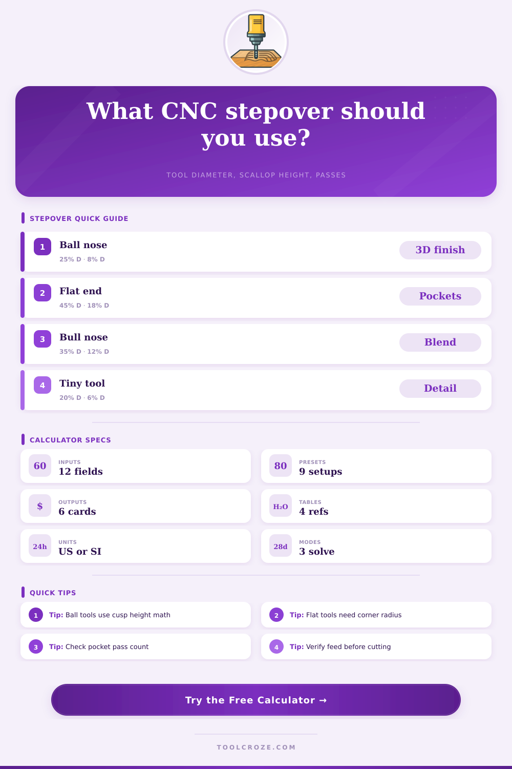
⚙ CNC Stepover Presets
Choose a realistic machining setup, then adjust cutter shape, material, surface finish target, feed speed, planned passes, and pocket width.
📐 Tool, Finish, And Pocket Inputs
Calculation Breakdown
⚒ Tool And Material Grid
🔢 Stepover Formulas
| Output | Formula | Imperial Units | Metric Units |
|---|---|---|---|
| Stepover distance | Step = diameter × percent / 100 | in | mm |
| Ball or radius scallop | h = R - sqrt(R² - (step / 2)²) | in cusp height | mm cusp height |
| Step from scallop | Step = 2 × sqrt(2Rh - h²) | Uses tool radius in | Uses tool radius mm |
| Pocket lanes | 1 + ceiling((width - diameter) / step) | Whole pass count | Whole pass count |
📏 Surface Finish Target Table
| Finish Target | Typical Scallop Limit | Common Stepover Range | Best Tool Match |
|---|---|---|---|
| Roughing | 0.0030 in / 0.076 mm | 25% to 55% of diameter | Flat or bull nose end mill |
| General shop finish | 0.0015 in / 0.038 mm | 12% to 30% of diameter | Flat, bull, or ball end mill |
| Semi-finish | 0.0008 in / 0.020 mm | 8% to 18% of diameter | Ball or bull nose end mill |
| Fine finish | 0.0004 in / 0.010 mm | 5% to 12% of diameter | Ball nose with short stickout |
| Polish or mold prep | 0.0002 in / 0.005 mm | 3% to 8% of diameter | Small ball nose finishing tool |
🛠 Material And Tool Reference
| Material | Finishing Stepover Bias | Starting Feed Style | Watch Point |
|---|---|---|---|
| Aluminum 6061 / 7075 | Medium, 8% to 20% D | Higher feed with chip evacuation | Built-up edge and recutting chips |
| Mild steel | Conservative, 6% to 16% D | Moderate feed, stable engagement | Rubbing if chip load is too low |
| Stainless steel | Small, 5% to 12% D | Positive feed and coolant | Work hardening and tool heat |
| Acrylic / plastics | Medium, 10% to 25% D | Sharp tool with real chip thickness | Melting from rubbing |
| Hardwood / MDF | Moderate, 12% to 35% D | Router-style feed by chip load | Fuzz, tearout, and dust extraction |
📋 Pocket Width And Pass Planning
| Pocket Situation | Pass Planning Rule | Stepover Note | Result To Check |
|---|---|---|---|
| Narrow slot under tool diameter | One lane may cover the width | Slot load can be heavy | Feed and chip evacuation |
| General pocket clearing | Use required passes from width | 20% to 45% D is common | Coverage and MRR |
| Finishing floor pass | Use scallop target mode | 5% to 18% D is common | Scallop versus target |
| Fixed number of passes | Use pass solve mode | Step = remaining width / gaps | Stepover percent warning |
💡 Practical Stepover Tips
Stepover is the distance that the tool move sideways in relation to the workpiece between passes. The stepover will have an effect upon the quality of the surface finish of the component that is being manufacture, as well as the total amount of time that it take to complete the component. If the stepover is large, then the tool will leave large cusp on the component that is being manufactured.
The cutting of these large cusps will create a rough component that will require more manual finish operations to improve the quality of the component. If the stepover is small, then the tool will leave small cusps on the component, and these small cusps will result in a smoother component that requires less manual finishing operation. The stepover percentage can be expressed as a percentage of the tool diameter, but the height of the scallops that are create will depend upon the shape of the tool.
Choosing the Right Stepover for a Good Finish
For instance, if you use a ball endmill, the height of the scallops will be different than if a flat endmill is used. This is due to the different shape of the two different tools; the two endmills have different geometries and radii at the corners of the endmills. In general, there is always a trade-off between the amount of time that the machine will spend cutting the component and the quality of the finish that is created.
The type of material that is to be cut will also impact the choice of the size of the stepover. Materials like aluminum allow for a larger stepover because the aluminum chip easily and does not work harden as easy as other materials. On the other hand, materials like stainless steel and titanium will require a smaller stepover for the component because the cutting of those materials will result in the buildup of heat and the cutting edge of the tool.
Materials like plastic will require a moderate stepover; too small of a stepover will result in the tool rub against the plastic and melting it, while too large of a stepover will result in the tool tearing the plastic instead of cutting it. The width of the pocket that is to be cut will also have an impact upon the choice of the size of the stepover. If you know the width of the pocket and the number of passes that are to be made with the tool, you may calculate the stepover that will produce the desired width of the pocket.
It is possible that the stepover that is calculated will result in a scallop height that is larger than the target height for that component. In this case, the number of passes and the scallop height should be compare at the same time to determine if the toolpaths meet the requirement for that component. In addition to stepover, feed speed and spindle RPM will also impact the cutting operations.
If the feed speed is too light when cutting a stiff material, the cutting tool may rub against the component instead of cutting into the component. If the feed is too aggressive for a tool on a machine that is not rigidly construct, the tool may deflect from the component that is being cut. These deflected tools will not result in the toolpath create scallops of the same height as those that are theoretically calculated.
Many people makes mistakes using toolpaths that have not been calculated for the specific component that is to be manufactured. One mistake is to use the same percentage for stepover for every job. This percentage will have to change if the diameter of the tool change or if the material change.
Another mistake is to only calculate the height of the scallop created by the toolpath and to ignore checking if the calculated stepover will fit within the width of the pocket. Both of these mistakes can be avoided by using a calculator to determine both the height of the scallops and the stepover for the toolpaths simultaniously. To use this process effectively, the first decision that must be made is the target for the finish of the component.
Based off the type of finish that is required, the tool that is to be used and its diameter will enable the calculation of the required stepover for the component. Finally, it is also important to check if this calculated stepover will fit within the width of the pocket. If the calculated stepover will not fit within the pocket, or if the height of the scallops is too great, then another decision must be made regarding the tool that will be used or the finish that will be placed upon the component; either of these change will impact whether the toolpath calculations are acceptable or not.