Have a Bosch 18v battery you’re looking to repair or do some other kind of work on? A pinout diagram and extra details about the interior will make jobs like that much easier.
Luckily, that’s what I’m here to share today! I did some tinkering with my Bosch 18v battery and made a pinout diagram for its wiring. I’ll share it below, along with other important things!
Bosch 18v Battery Wiring Diagram Pinout
I can’t explain much until you see the diagram itself, so let me share that with you first. After you take a look at it, keep reading to find an explanation for the parts inside the diagram.
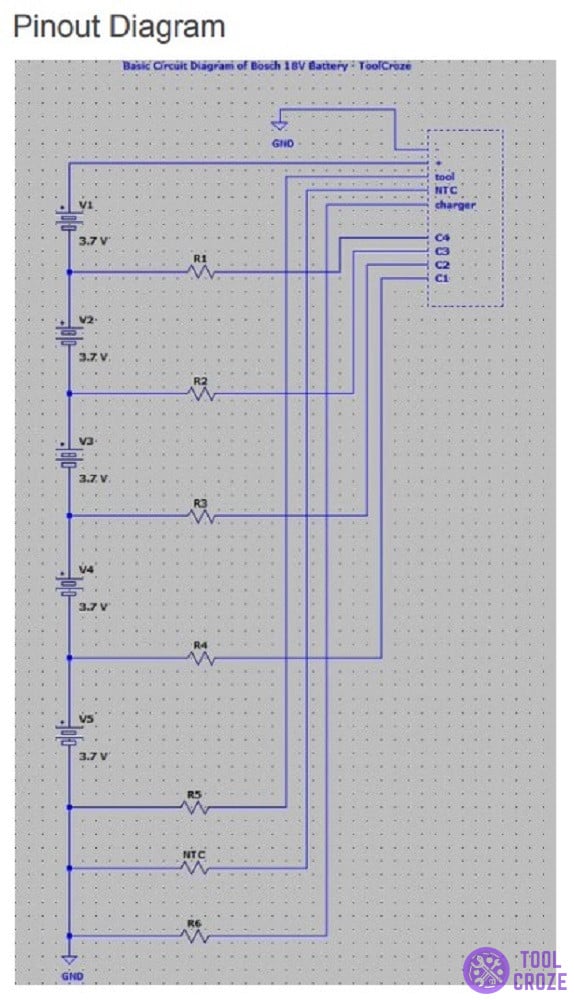
That up there is a pinout diagram for the Bosch 18v. It covers the main outline of the battery’s inner workings, along with all the most important components that play a part in its functioning.
Now, if you don’t know what exactly it is that you’re looking at, here’s a rundown of what you see in the diagram and what it all means:
GND: In the pinout diagram, this particular lettering is an acronym for “ground”. It is a zero-potential reference point that acts as the negative terminal of the battery.
The negative terminal is one of the most important parts of a battery. It is responsible for pushing electrons through the circuit towards the positive terminal, creating an electric current.
+: The opposite of a negative terminal is the positive terminal, which is marked in the diagram with the plus sign (+). This is the positive battery connection point.
Related: Reset Bosch 18V Battery: Ways to Do It
This terminal is the destination point for the electrons sent through the negative terminal, which I told you about just a bit ago.
C#: This is the symbol for a capacitor inside the Bosch 18v battery. A capacitor is a terminal used to balance the battery’s charges.
Each capacitor is numbered for differentiation. All capacitors play the same role, just in different parts of the battery. Together, they work with B- and B+.
R#: Across the diagram, the “R” symbol is for the resistors. Resistors are components that limit the electrical currents’ flow in order to provide a specific voltage.
Each resistor is assigned a number just like the capacitors are. Similarly, they all do the same job regardless of number, just at different parts of the battery.
V#: V stands for the battery connected to a circuit board. When there is more than one, each battery is assigned a number in a series.
The voltage number beside each battery is the voltage that the specific battery in question carries. The voltage determines the performance of the battery.
NTC: And finally, this symbol here is for the Negative Temperature Coefficient Thermistors.
Negative Temperature Coefficient Thermistors are resistors that limit a current across a circuit board. Their resistance decreases as temperature increases.
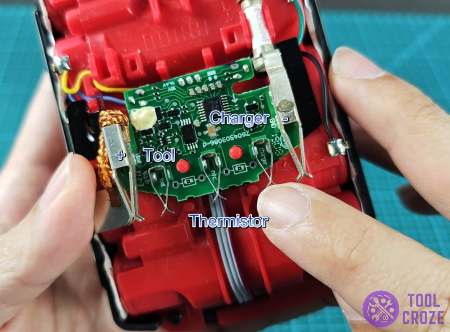
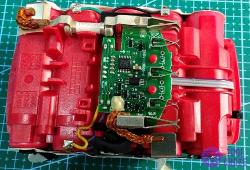
Inside The Bosch 18v Battery Adapter
Moving on, there are a couple of other things you should know about the inner workings of these things. Starting with the fact that the battery’s circuit board contains a series of six resistors.
On it, the R6 resistor is tied to the charger, and the R5 resistor is tied to the tool. The B- terminal is tied to the C1 and C3 pins.
The B+ terminal is tied to the C2 and C4 pins. Finally, the NTC Thermistor is tied to the B+ and B- pins through capacitors 1-4.
On the circuit board, these are the voltages of each of the terminals and pins:
- Positive and negative terminals = ∼20V
- Negative terminal with tool, thermistor, and charger pin = 0V
- Positive terminal with tool, thermistor, and charger pin = 20V
- Negative terminal and C1 contact point = 4V
- Negative terminal and C2 = 8V
- Negative terminal and C4 = 16V

Do you know what size the fuse is? I need to replace on but there are no amp markings, just the part number which doesn’t return any search engine information (bosch part no: 1 607 502 814). Thanks.