🔩 Bolt Stress Calculator
Estimate tensile stress area, installation preload, combined service stress, and proof-load margin for common SAE, ASTM, and ISO bolted joints.
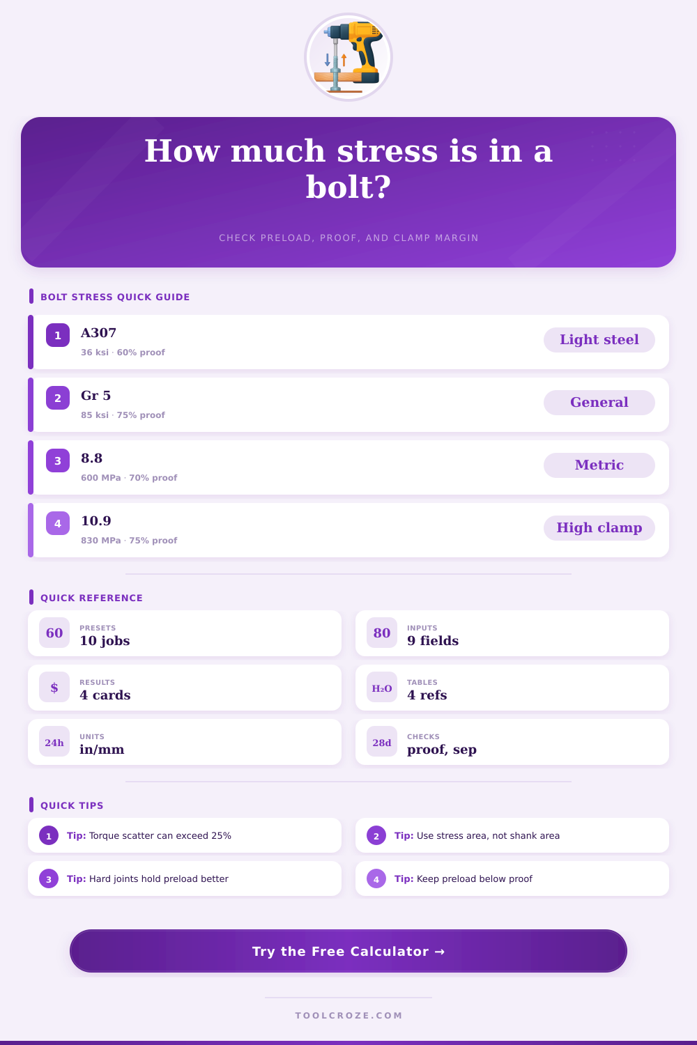
📌 Preset Joint Cases
⚙ Bolt and Load Inputs
🎯 Results
🗂️ Bolt Grade Comparison Grid
📊 Reference Tables
| Bolt spec | Proof strength | Ultimate strength | Typical target preload | Notes |
|---|---|---|---|---|
| ASTM A307 | 36 ksi | 60 ksi | 55–65% proof | General anchorage and light duty steel |
| SAE Grade 2 | 55 ksi | 74 ksi | 60–70% proof | Low-cost carbon steel joints |
| SAE Grade 5 | 85 ksi | 120 ksi | 70–75% proof | Common machine frames and brackets |
| SAE Grade 8 | 120 ksi | 150 ksi | 75–80% proof | High-strength machinery connections |
| ASTM A325 | 85 ksi | 120 ksi | 70% proof | Structural bolts with controlled pretension |
| ASTM A490 | 120 ksi | 150 ksi | 70–75% proof | Heavy structural splice joints |
| ISO 8.8 | 600 MPa | 800 MPa | 65–75% proof | Metric machine joints and skids |
| ISO 10.9 | 830 MPa | 1040 MPa | 70–80% proof | Higher clamp, fatigue-sensitive joints |
| Joint condition | Nut factor K | Expected scatter | Use case |
|---|---|---|---|
| Dry black steel | 0.20–0.24 | High | General shop assembly |
| Light oil | 0.16–0.20 | Medium | Machine base and covers |
| Zinc plated | 0.18–0.22 | Medium | Utility and outdoor brackets |
| Waxed structural | 0.14–0.18 | Lower | Tension-controlled structural bolts |
| Gasketed joint | 0.18–0.24 | High | Soft flange assemblies |
| Nominal size | UNC / coarse pitch | Metric coarse pitch | Typical use |
|---|---|---|---|
| 1/2 in / M12 | 13 TPI = 0.0769 in | 1.75 mm | General brackets and skids |
| 5/8 in / M16 | 11 TPI = 0.0909 in | 2.00 mm | Base frames and flanges |
| 3/4 in / M20 | 10 TPI = 0.1000 in | 2.50 mm | Structural splices and heavy bases |
| 7/8 in / M24 | 9 TPI = 0.1111 in | 3.00 mm | Large machinery and towers |
| Preset style | Torque trend | Load share C | Design note |
|---|---|---|---|
| Machine frame | Moderate | 0.20–0.30 | Stiff clamped members keep bolt load low |
| Gasketed flange | Higher | 0.35–0.50 | Soft members transfer more service load into the bolt |
| Anchor rod | Low to medium | 0.40–0.60 | Concrete settlement and embedding can reduce clamp |
| Structural splice | Controlled | 0.20–0.25 | Pretension aims to resist slip before tension rises |
📈 Material and Spec Comparison
Low-carbon bolts
Specs: A307, Grade 2
Best for: Light anchors, covers, noncritical brackets
Watch: Lower proof means clamp loss arrives sooner under cyclic load.
Medium-strength bolts
Specs: Grade 5, ISO 8.8
Best for: Equipment bases, guards, skid frames
Watch: Good balance of preload and ductility for daily machinery joints.
High-strength bolts
Specs: Grade 8, A490, ISO 10.9
Best for: Dynamic joints, structural splices, compact clamp packages
Watch: Better clamp density, but thread damage and overtorque margins are tighter.
Joint stiffness effect
Hard joint: Lower C, more clamp reserve
Soft joint: Higher C, more bolt load rise
Rule: Reducing joint compliance often helps fatigue more than simply increasing grade.
💡 Practical Tips
This calculator estimates bolt preload, service stress, and proof margin from diameter, thread pitch, torque, and external load so you can compare common joint cases before final engineering review.
Bolts is used to hold structures and machine bases together, and bolts must maintain a specific amount of tension to keep the structures or machines together. The tension that bolts maintains is referred to as the preload. The preload is the force that the bolt apply to the structure it is attaching to.
This preload create a form of compression within the structure that resists the external forces that may act upon it. When bolts are tightened, the preload are created. This preload allow the structure’s materials to endure external loads upon those structures rather than the bolt itself.
Bolt Preload and Joint Safety
If the preload is too low for an amount of external loads that are placed upon the structure, the bolt will experience too much stress, which will result in the bolts failure. The relationship between torque and preload is determined by a mathematical equation. The equation is expressed as the torque applied to the bolt is equal to the nut factor multiplied by the preload created by the bolt times the diameter of the bolt.
The nut factor, also referred to as an K factor, is a value that calculates the effects of friction between the threads of the bolt. The friction between the bolt threads can change the nut factor. For example, if a bolt has dry threads, it will have a higher nut factor than if the threads of the bolt is lubricated.
Because the nut factor is reduced with lubrication, a lubricated bolt will reach a higher preload with the same amount of applied torque. However, if the bolt is lubricated too much, it can reach a preload that is too high for the proof load of the bolt. The bolt threads have a specific geometry that affects the amount of stress that the bolt will endure.
For bolts, the tensile stress area should be used instead of the diameter of the bolt. The tensile stress area is the area of the bolt that is subject to tension. Because of the threads on the bolt, the tensile stress area will be smaller than the full diameter of the bolt.
To calculate the tensile stress area, you must account for the pitch of the bolt threads. The pitch of the bolt threads must be correctly convert to the correct imperial or metric units. The pitch of the bolt threads will affect the tensile stress area of the bolt; the finer the threads on the bolt, the greater tensile stress area of the bolt.
External loads will place stress upon the bolt, but the amount of stress that is placed upon the bolt depend upon the stiffness of the materials that are being joined together. If the materials that are being joined together are under pure tension, then all of the external loads will be placed upon the bolt. However, if there are multiple materials that is joined together into a structure, the stiffness of those materials will determine the amount of external load that is placed upon the bolt.
The stiffness of each material is mathematically represented as the stiffness constant, or the C factor. Materials that have a high stiffness, such as steel plates, will have a low C factor. A low C factor indicates that the bolt will endure a low portion of the external loads of the structure.
Materials that are softer than steel, such as gaskets, will have higher C factors, indicating that the bolt will have to endure a higher portion of the external loads of the structure. Every bolt has a limit to the amount of stress it can endure without permanently stretching the metal of the bolt. This amount of stress is referred to as the proof load of the bolt.
The preload of the bolt should always be lower than the proof load. For most bolts, the target preload will be between 70 and 75 percent of the proof load. If the preload is allowed to be higher than the proof load of the bolt, the bolt will experience a permanent stretch.
A permanently stretched bolt will fail structurally because it will no longer be able to maintain the necessary tension. Depending upon the grade of the bolt, each will have a different proof load. Grade 8 bolts will have a higher proof load than Grade 5 bolts.
Over time, vibrations may occur that will cause the preload of the bolt to decrease. The decrease in preload will place the bolt at risk for fatigue failure. Fatigue failure occurs with repeated applications of external loads to the bolt.
High preload will protect the bolt from experiencing fatigue failure. The type of joint that is used will also affect the preload of the bolt. For example, joints that use gaskets or are embedded into concrete will experience settling of those structures.
This settling of the joint will cause a reduction in the preload of that joint. To ensure that a joint with bolts is reliable, there are several factors that must be accounted for. You must account for the tensile area of the bolt to ensure that the strength of the bolt is not overestimated.
The nut factor must be accounted for, especially if the bolt is lubricated. The stiffness of the joint must be accounted for to determine how much external load the bolt will endure. By accounting for each of these factors, it is possible to ensure that the preload force of the joint is within a safe range.
If the preload of the joint is within a safe range, the joint will not fail due to excessive stress or fatigue.