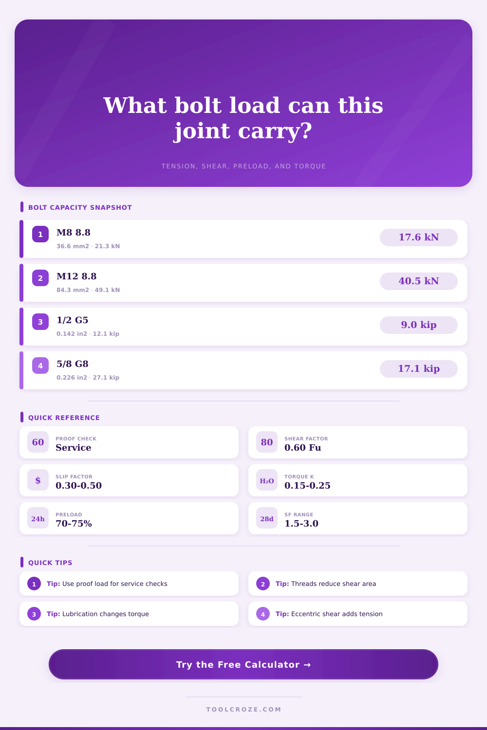
Bolt Load Capacity Calculator
Estimate bolt tension capacity, shear capacity, preload, tightening torque, and combined utilization from bolt size, grade, load case, and joint geometry.
Calculated Bolt Capacity
Full Calculation Breakdown
| Specification | Proof Stress | Minimum Tensile | Calculator Use |
|---|---|---|---|
| ISO Class 4.6 | 225 MPa | 400 MPa | Low-strength service bolts |
| ISO Class 8.8 | 580 MPa | 800 MPa | General structural metric bolts |
| ISO Class 10.9 | 830 MPa | 1040 MPa | High-strength machinery joints |
| ISO Class 12.9 | 970 MPa | 1220 MPa | Socket head and high clamp joints |
| SAE Grade 2 | 55 ksi | 74 ksi | Light-duty inch hardware |
| SAE Grade 5 | 85 ksi | 120 ksi | Medium-strength inch hardware |
| SAE Grade 8 | 120 ksi | 150 ksi | High-strength inch hardware |
| ASTM F3125 A325 | 92 ksi | 120 ksi | Structural steel connections |
| ASTM F3125 A490 | 130 ksi | 150 ksi | High-strength structural connections |
| Stainless A2-70 / A4-70 | 450 MPa | 700 MPa | Corrosion resistant metric bolts |
| Metric Bolt | Coarse Pitch | Tensile Stress Area | Class 8.8 Proof Load |
|---|---|---|---|
| M6 | 1.00 mm | 20.1 mm2 | 11.7 kN |
| M8 | 1.25 mm | 36.6 mm2 | 21.2 kN |
| M10 | 1.50 mm | 58.0 mm2 | 33.6 kN |
| M12 | 1.75 mm | 84.3 mm2 | 48.9 kN |
| M16 | 2.00 mm | 157 mm2 | 91.1 kN |
| M20 | 2.50 mm | 245 mm2 | 142 kN |
| M24 | 3.00 mm | 353 mm2 | 205 kN |
| M30 | 3.50 mm | 561 mm2 | 325 kN |
| UNC Bolt | Thread Count | Tensile Stress Area | Grade 5 Proof Load |
|---|---|---|---|
| 1/4 in | 20 TPI | 0.0318 in2 | 2.70 kip |
| 5/16 in | 18 TPI | 0.0524 in2 | 4.45 kip |
| 3/8 in | 16 TPI | 0.0775 in2 | 6.59 kip |
| 7/16 in | 14 TPI | 0.1063 in2 | 9.04 kip |
| 1/2 in | 13 TPI | 0.1419 in2 | 12.1 kip |
| 5/8 in | 11 TPI | 0.2260 in2 | 19.2 kip |
| 3/4 in | 10 TPI | 0.3340 in2 | 28.4 kip |
| 1 in | 8 TPI | 0.6060 in2 | 51.5 kip |
| Check Item | Typical Value | Formula Role | When To Adjust |
|---|---|---|---|
| Preload target | 70% of proof | Clamp force = proof load x preload ratio | Use lower values for reused or uncertain hardware |
| Nut factor K | 0.20 clean dry | Torque = K x clamp force x diameter | Lubrication can reduce torque sharply |
| Threaded shear area | Tensile stress area | Conservative shear plane area | Use shank area only when plain shank is in shear |
| Shear strength estimate | 0.60 x Fu | Nominal shear from tensile strength | Use project code values for final design |
| Combined loading | Elliptical ratio | sqrt((T/Ta)^2 + (V/Va)^2) | Useful for screening mixed tension and shear |
| Slip check | 0.30 to 0.50 mu | Slip resistance from preload and friction | Needs surface class and code-specific factors |
There are many properties for each material listed in both SAE and ISO standards. This isn’t necessary to create a safe mechanical connection.
To have a safe connection, you must understand that bolt isn’t just a connector. It is actualy a spring-loaded connector. You stretch it until it grips two plates hard enough to keep them from moving apart under a load.
How Bolts Work
Once you enter your grade and diameter into the calculator above, it will do the math for you so you don’t have to thumb through the manuals searching for proof loads and stress areas. More important then what the calculation tells you is understanding what parameters actualy affect safety of your joint.
Almost everything you need to know about the potential of a bolt’s strength are marked on its head in grade. That’s because an 8.8 metric bolt is rated at 800 megapascals tensile strength with a yield point representing 80 percent of that. This makes it the most common grade for most general structural steelwork application. A Grade 5 imperial bolt (look for proof stress of 85 ksi) represent another level up from there. These aren’t made-up numbers. They represents the maximum preload you can safely apply without stretching thread portion of the bolt beyond recovery. Most folks don’t realize just how much tension a modestly sized diameter bolt will endure when correctly torqued.
The caveat here is that capacity are defined by the weak spot, which is typically the threaded part of the shank and not smooth shank. The app also figures tensile stress area based off the diameter you type in. Threads take away material so tensile stress area are not the same as gross cross section. Depending on where that shear plane falls, it will be either smaller (the threads) or larger (the shank), and that have a big impact on shear capacity. For flange connections it’s a subtle but critical difference. The chart on the page puts this into perspective with common sizes, it shows tensile stress area for M12 is almost 25 percent less after threading.
Is the bolt head or nut on the outer surface of the connection? Does the shear plane cut through the threads or unthreaded shank? If the thread section is within the grip length, you’ll have higher shear strength. If it’s exposed, you need to consider lower area.
Where theory meets messy reality is torque. Usually, a nut factor of 0.20 (clean, dry threads) are used by the calculator to estimate how much torque is needed to obtain the desired clamp load. That nut factor includes thread friction and also the friction below head of the nut. Add a drop of anti-seize compound and the nut factor drops to 0.12, so much less torque is required to get same clamp load. Apply the dry-torque values on a lubricated bolt and you’ll over-tighten it. The result is snapped bolts and stripped threads when you try to install next bolt. A frequent error in field work happen when maintenance crews think the torque spec stay the same no matter what surface conditions are. Modify the input nut factor if using any lubricant.
The other twist is combined loading. A bolt isn’t subjected to either pure tension or pure shear very often. Eccentric loads generates moments which try and shear a bolt while also pulling it into tension. This is where the calculator checks combined demand using an elliptical interaction formula. It makes sure that the combined use ratios does not exceed one. In the case of a cantilevered bracket, the outer bolts will see most of the tension. The inner bolts might just stays in contact with the gusset plate. You should of confirm that total preload is enough to maintain closure on the joint for all those varying stresses. When the clamp force can’t overcome the external load, the joint opens up and then the bolt has to handle the full dynamic load. Fatigue begins at that point.
Safety factors exist for a reason. Static loads use a factor of 2.0 as a default, but impact or vibration need more safety margin. You can set that accordingly for your own application in the tool. Remember the allowable load isn’t a rigid limit. It’s a screen value. Professional review is needed for final design. But it gives you a good sense upfront if the fasteners you’re thinking about using will hold up.
Start at the grade. Then look at the area. Then consider the friction. The rest falls into place.
A well-designed joint comes from clamp force, not bearing. Hold those plates together.