Bend Allowance Calculator
Calculate sheet metal bend allowance, neutral axis, outside setback, bend deduction, developed flat length, and quantity allowance from bend angle, inside radius, thickness, K-factor, material, and bend method.
⚙ Units And Bend Presets
📏 Bend Inputs
Formula Breakdown
🔧 Material And Method Specs
📊 K-Factor Reference
| Bend method | Typical K-factor | Radius condition | Layout note |
|---|---|---|---|
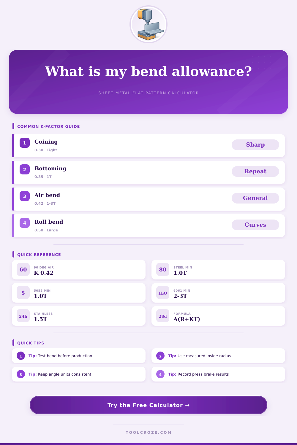
| Coining | 0.28-0.33 | Tight radius | High tonnage, low springback |
| Bottoming | 0.33-0.38 | Near 1T radius | Repeatable press brake work |
| Air bending | 0.38-0.45 | 1T to 3T radius | Most common shop setup |
| Wipe bending | 0.35-0.42 | Tooling controlled | Flanges and panel edges |
| Roll bending | 0.45-0.50 | Large radius | Neutral axis moves outward |
| Material | Suggested min radius | Starting K-factor | Springback cue |
|---|---|---|---|
| Mild steel | 1.0T | 0.42 | Low to moderate |
| Cold rolled steel | 1.0T | 0.40 | Moderate |
| Galvanized steel | 1.0T | 0.42 | Coating may crack |
| 304 stainless steel | 1.5T | 0.43 | Higher springback |
| 5052-H32 aluminum | 1.0T | 0.41 | Good forming grade |
| 6061-T6 aluminum | 2.5T | 0.44 | Use generous radius |
| Copper sheet | 0.5T | 0.38 | Soft and formable |
| Cartridge brass | 1.0T | 0.39 | Grain direction matters |
| Bend angle | Radians factor | Setback multiplier | Use case |
|---|---|---|---|
| 30° | 0.5236 | tan 15° | Shallow offset flange |
| 45° | 0.7854 | tan 22.5° | Trim and bracket bends |
| 60° | 1.0472 | tan 30° | Architectural panels |
| 90° | 1.5708 | tan 45° | General sheet metal parts |
| 120° | 2.0944 | tan 60° | Open channel layouts |
| 135° | 2.3562 | tan 67.5° | Obtuse flashing bends |
| Preset | Material and thickness | Radius and angle | Typical purpose |
|---|---|---|---|
| 16 ga steel 90 air | Mild steel, 0.0598 in | 0.063 in, 90° | Shop brackets |
| 5052 box flange | 5052-H32, 0.080 in | 0.080 in, 90° | Aluminum box sides |
| 304 cover bend | Stainless, 0.048 in | 0.075 in, 90° | Equipment covers |
| 22 ga duct bend | Galvanized, 0.030 in | 0.032 in, 90° | Duct flanges |
| 6061 large radius | 6061-T6, 0.125 in | 0.375 in, 90° | Crack-sensitive bends |
💡 Shop Notes
Most sheet metal failures begin when the shape appears right on paper but won’t form when bent into place. It’s either too short or the flanges don’t reach. Maybe the radius was too small for the type of steel used so the corners rip apart.
What we have here is a combination of physics and geometry. Intuition has little use at such times. Adding up the lengths of the legs doesn’t mean you’ll end up with something that work. Metal on both sides of the bend will compress and stretch. Somewhere between those areas is what I call the neutral axis. That’s a line where nothing will stretch or shrink. Knowing exactly where it sits becomes the difference between a prototype and a pile of scrap.
Why Sheet Metal Bends Are Hard to Plan
Below that, a calculator will do it for you (above). But knowing how it works are far more important than simply pushing the button. The one thing most people don’t understand about sheet metal layout is the k-factor. That’s actualy the spot along the material thickness where the neutral axis is, expressed as a ratio of the material thickness. If your k-factor is lower, then the neutral axis remains nearer to the inside face of the material; that happens when you’re using something like high pressure coining, crushing the material into the die. Standard air bending results in little distortion of the material and pushes the neutral axis out towards the outer surface, to a higher k-factor. For mild steel, it tends to be roughly 0.42 in that case.
By choosing the bend type in the tool, you establish that starting point. The reference table on the page illustrates the difference between normal air bending allowance versus what coining requires.
Before we get into any angles, there’s another consideration: what material do you use? Aluminum 6061-T6 is strong but brittle in sharp bends; if the inside radius is too small compared to the sheet thickness, it will crack. To prevent that, make the radius large enough to let the metal flow without breaking. Mild steel can take a tight radius, which saves both material and space. Copper wants to bend, and stainless steel resists bending by springing back significantly. Depending on what you select, the tool will adjust those settings to match, but knowing why you’re adjusting them is important.
No matter how much you calculate the minimum radius for a given alloy, the part will still crack at the root. Precision can be reduced due to springback, which is the metal’s desire to go back to being flat after removing pressure on a press brake. This is more pronounced with harder metals (e.g., hardened aluminums and stainless steels) than with mild steels. One solution is over bending to compensate for the springback. Another is using closed-die bottoming, which minimizes springback by keeping the angle under pressure throughout the full length of the stroke.
That’s why shop notes are important here. The K-factor from textbooks may differ from that of your machine set up. The grain direction of the sheet, width of die opening, and tooling nose radius will affect results.
The formula is flange length minus bend allowance equals flat pattern length minus deductions. That sounds easy enough, but then you find out that drawing outside dimensions makes it easy to measure but not correct. How do they get away with this? Well, when draftspeople draw something, they dimension the outside legs. Our calculator takes that and figures out what it should of be based off the arc length at the neutral axis. That gives you a developed length for the flat. This tells you the yield of your material if you’re cutting blanks from large sheet or coil stock.
Making a mistake in a couple thousandths of an inch at each bend really starts to add up if you have several bends in one part. There are no shortcuts with testing. Always make a test coupon out of the same heat of material that you plan on producing the product from. Measure the flange height after bending the piece and then work backwards from there to determine your actual K-factor. Write down the number. Every press brake is a little different so generic tables are never as good as what you can get by doing your own tests. Log settings for each job. When you go back to do something similar months later it will save some time.
Making sheet metal accurately isn’t about guesswork. It’s about noting what actualy happened and tweaking from there. The geometry will do what you tell it to do. If you set things up correctly they will go together. Holes mate with holes and you won’t waste material trying stuff twice. It does the algebra for you so you can focus on the design intent. Use reasonable bend techniques for your shop tools, take accurate measurements and be realistic about what your materials can handle. Frustration on the shop floor means little planning at the drawing board. Respect the variables and the geometry will behave predictably.