Belt Wrap Angle Calculator
Calculate open or crossed belt wrap angle, pulley contact arc length, belt length, speed ratio, Euler tension ratio, and practical slip risk from real belt-drive geometry.
Belt wrap and slip results
Calculation breakdown
| Belt type | Effective friction range | Useful wrap target | Common note |
|---|---|---|---|
| Rubber V-belt in sheave | 0.45 to 0.70 effective | 150 to 180 degrees | Groove wedge boosts grip but alignment matters |
| Rubber flat belt | 0.30 to 0.45 | 170 to 210 degrees | Needs good crown, tension, and clean pulley faces |
| Leather or raw-edge flat belt | 0.25 to 0.40 | 180 to 220 degrees | Moisture and dressing change friction quickly |
| Poly-V belt | 0.40 to 0.60 effective | 140 to 180 degrees | Many ribs share load across a small height |
| Timing belt tooth drive | Positive pitch engagement | 90 to 160 degrees | Tooth count in mesh is more important than friction |
| Urethane round belt | 0.25 to 0.45 | 170 to 220 degrees | Light-duty drives need stretch and clean grooves |
| Small pulley wrap | Friction drive meaning | Likely adjustment | Watch for |
|---|---|---|---|
| 180 degrees or more | Strong contact for most friction belts | Keep geometry, confirm belt length | Over-tension from short belt selection |
| 150 to 179 degrees | Normal V-belt and poly-V range | Use correct tension and alignment | Glazing, dust, and small pulley heat |
| 130 to 149 degrees | Marginal for higher torque friction drives | Increase center distance or add idler wrap | Start-up squeal and speed loss |
| Under 130 degrees | High slip risk unless positive drive | Use larger small pulley or redesign centers | Belt heat, rapid wear, poor tracking |
| Drive example | Small pulley diameter | Typical belt width | Practical speed range |
|---|---|---|---|
| Fractional HP V-belt | 2.0 to 4.0 in | 3L, 4L, A section | 1000 to 5000 ft/min |
| Shop machine A/B V-belt | 3.0 to 7.0 in | 1/2 to 5/8 in | 2000 to 6500 ft/min |
| Flat leather line shaft | 4.0 to 12.0 in | 1 to 4 in | 1500 to 4500 ft/min |
| HTD timing belt | 18 to 30 teeth | 9 to 25 mm | Vendor rating required |
| Round urethane belt | 1.0 to 3.0 in | 1/8 to 3/8 in | Light-duty conveyors |
| Preset | Mode | Pulley pair | Design intent |
|---|---|---|---|
| Bench grinder V-belt | Open | 3.0 x 5.5 in | Moderate reduction from a 1725 RPM motor |
| Lathe countershaft | Open | 2.5 x 7.0 in | Large ratio with enough wrap for start-up torque |
| CNC timing belt | Open | 24 x 60 mm | Checks arc length and tooth engagement proxy |
| Crossed fan belt | Cross | 4.0 x 4.0 in | Opposite shaft rotation with high contact angle |
| Large reduction | Open | 2.75 x 12.0 in | Small pulley wrap becomes the limiting geometry |
So now you have a machine which converts power to movement. With the right motor specs and pulley ratios selected, it look solid on paper. But as soon as you fire her up, she belts (get it?). And if that belt slips under a load, or even worse, starts to squeal, don’t blame the belt; the problem typicaly lies in the wrap angle.
This little bit of geometry tell you what percentage of pulley circumference makes contact with the belt. It basically tells you how much torque you can absorbs before the thing fails. You’ll find the calculator up top that calculates tension ratios and contact arcs given your own set of geometry. But that’s just half the engineering; it’s when you understand what those numbers represent that the real math kicks in.
Why Wrap Angle Matters for Belts
The wrap angle is a direct measure of grip. For a friction drive such as a flat belt or v-belt, all the power transfer come from the normal force between pulley surface and the belt. If there’s not enough to prevent sliding then the load must exceed what that small arc can handle, and off she slides.
But not all pulleys behaves the same way here. The smaller pulley will always have the smaller wrap angle in a typical open drive setup. So geometry dictates this and it’s the small pulley that becomes the weak link where we’ll typically see slip starting out. And you may have a large pulley being the driven one with close to two hundred degrees of contact but if your driver pulley has only a hundred and twenty, then the entire system is bound by lower number.
A little more helpful is increasing the distance between the shafts at the belt’s center. By pulling the pulleys farther apart, it increases wrap angle which helps provide more contact with each pulley. You could also look into using a crossed belt, which offers other advantages but twists the belt to significantly increase the wrap angle on each pulley. It does twist the belts internally so there is more wear in that arrangement, but if your drive is high torque and low speed, the added contact may outweigh that disadvantage.
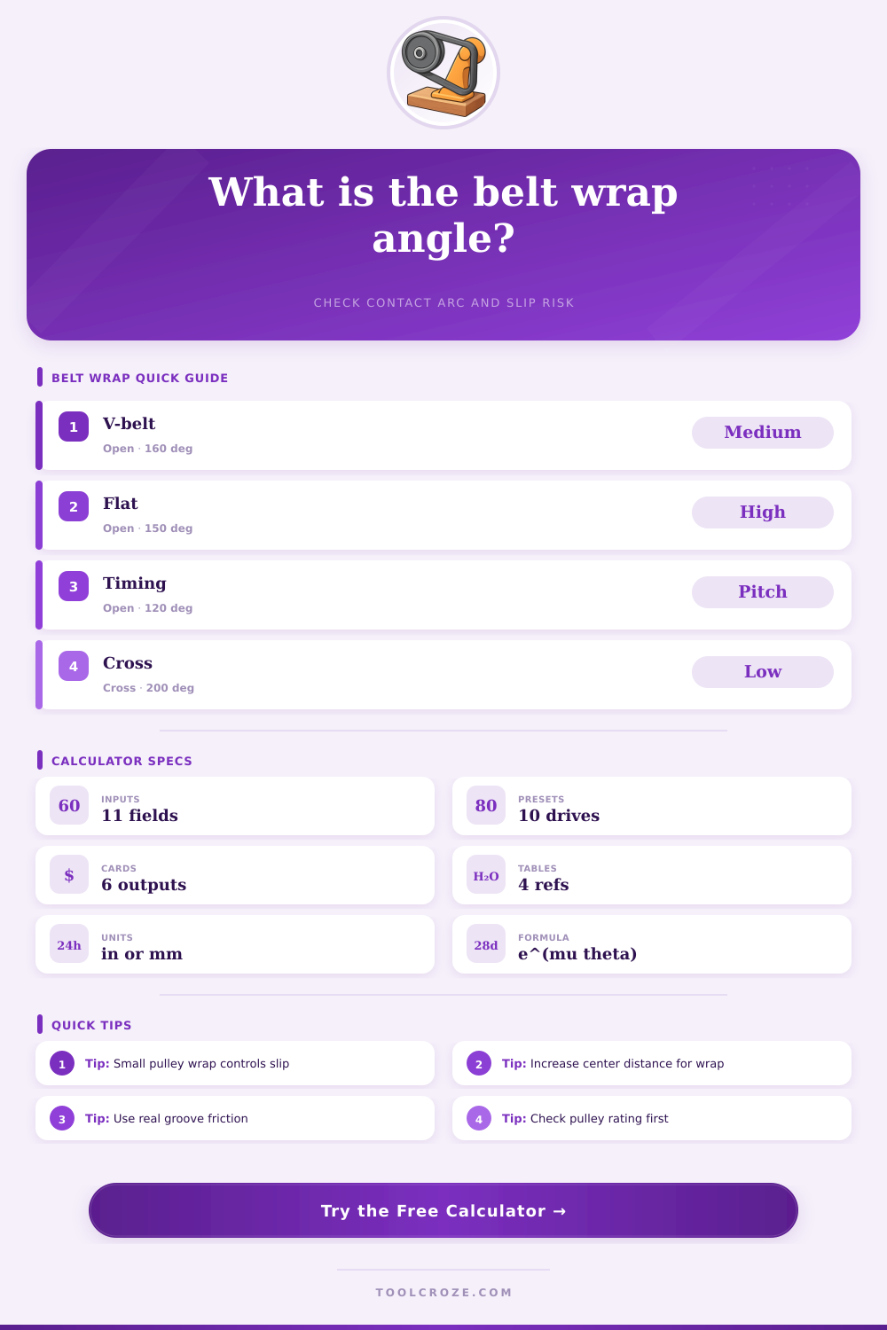
It also includes friction coefficients of each kind of material which can range considerably. For example, a flat leather belt only relies on the adhesive force between the belt and the sheave surface. In contrast, a groove in the sheave create a wedge effect that increases the friction for a V-groove rubber V-belt. Not all these different kinds of belts is equal; you can’t just throw any material into this equation expecting to get results. As seen in the table above, flat belts realy need higher wrap angles to work well. Timing belts can operate safely at far lower wrap angle because they don’t depend on friction but instead “lock” with teeth through positive engagement.
The other number I pay close attention to is slip risk: the tool finds that value based off your tension ratio, then compares it to normal safe zones. A high slip risk typicaly indicates a geometry issue. This is usually due to a geometry issue, such as too little wrap at the angle. This is more likely than a material issue, because there isn’t enough grip when there are not enough wrap angles. Even with the priciest industrial belt in existence, if they don’t have over one hundred and thirty degrees of wrap at the friction drive, it won’t matter.
An idler pulley is often less expensive than upgrading to something “better” in performance. Redesigning the layout would of been cheaper than chasing higher-performance materials. Even though belt drives appear to be nothing more than a rubber strap between two wheels, they’re really complicated systems of friction and geometry. The wrap angle must be just right so the belt runs smoothly at full load, does not slip and does not squeal or wear out early. When you put your machine under torque, you want your design to hold its ground. Check the wrap before you cut a single piece of metal to assure your design does what you intended it to do.