
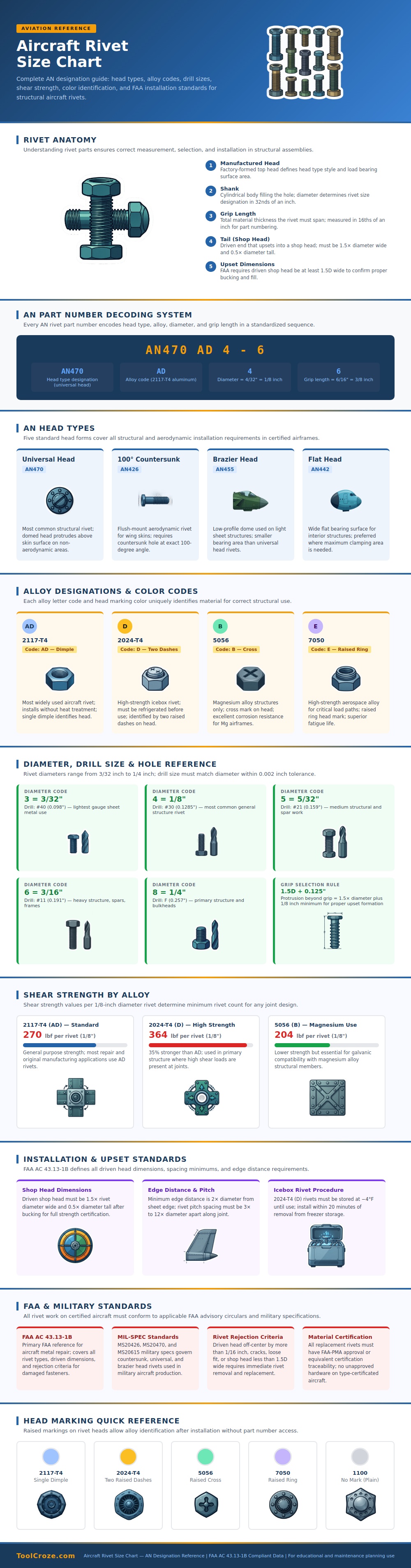
Rivets can seem like a simple thing. Anyone can tell which size one fits into a wing skin, right? Wrong. Each rivet has its own set of information in the letters and numbers etched into it. How does it know what it’s supposed to be used for? This chart explain rivet anatomy and how each part functions.
Every part, from the driven tail and manufactured head to the grip length and shank, hold an aircraft together while under incredible loads. When you see rows and rows of seemingly indistinguishable cylinders, your eyes will trick you into thinking they’re all the same. Unfortunately, that’s where expensive lessons happen. They aren’t all the same. Different materials has wildly varying characteristics so knowing how to read the code is essential. Two alloys may look alike initially but behave different under load.
How to Read Rivet Codes
Each fastener have its own history, which is called the part number. For example, AN470 denotes a universal head. The designation tells you it has a universal head, while the letters following it reveal the alloy composition. They’ll have codes such as AD or D representing different aluminum alloys. Decoding these codes becomes clear when looking at the chart. It explains visually how the diameter is represented in thirty-seconds of an inch, and the grip length are in sixteenths.
Why does this matter? Choosing the incorrect grip length result in a weak joint. It can also tear up the surrounding sheet metal when installed. What you want is for the rivet to fit snugly into the hole, with just enough tail material left over to form a good shop head on the back side.
It features different styles of heads that can be used, such as universal round heads used for general structure. Lighter assemblies often feature low-profile brazier heads. Aerodynamic surfaces with countersunk rivets are critical. Anything sticking out on an aerodynamic surface interrupt air flow and causes more drag. When you replace a small panel, air resistance is important. In high speed flight, every bump counts.
A few lines illustrate these shapes clearly. You can see the physical profile and know how it matches the structural need before picking up your hammer. That eliminates the need to guess which shape to use. You can choose a domed head for standard shear strength or a flat head to maximize bearing area.
The most important safety consideration of all may be alloy type. Color coded dots on the chart will quickly identify the type of alloy. A single dimple identifies 2117-T4 rivets, while two raised dashes denote the stronger 2024-T4 version. That’s important because the latter should of been refrigerated prior to installation. Anytime you leave those cold set fasteners sitting in room temperatures, they’re no longer mechanically sound. They’re already damaged and it happens before you even begin cranking on ’em.
Those head marks are highlighted in the graphic. That’s a quick guide for techs to double check alloy types so they know which one works with what without having to pull up a book. Get the wrong alloy and your structure could fail immediately when put under load; worse yet, you’ll face the threat of galvanic corrosion.
The chart gives you size codes by diameters with a list of the drill sizes used. Each one has a pretty tight tolerance as outlined on the chart. Drilling isn’t just a hole. You’re creating a specific socket for a part that supports load in flight. To get it right, the rivet needs to be the correct diameter +/-.001″ or thousandths of an inch using the same drill bit. If it’s too big, the rivet can be loose and transfer stresses unevenly. Eventually this results in fatigue cracks.
Each drill number is referenced to its corresponding size. No need to measure twice and cut once. When precision matters, it matters a lot. According to FAA guidelines for installation standards, the driven shop head must be at least one-and-a-half times the diameter of the rivet. That is adequate material to allow the fastener to upset correctly and lock the plates tightly together.
As you can see in the chart, spacing and edge distance are critical to proper riveting, too. Margins around the sheet edges should be sufficient to avoid tearing out, and you want to space your rivets so they shares the load well. Understanding this stuff takes an ordinary fix up and makes it a real, safe mod. When your eyes are no longer trained to see rivets as nothing more than nails, your craftsmanship soars.
Begin deciphering the markings on their heads, as well as their sizes and codes, which act like directions. That’s where the chart comes in. It’s the decoder ring. It’s your ticket from mute metal to plain-as-day data. And you leave feeling confident in your knowledge of what keeps it all connected.
