🔥 MIG Welding Gas Flow Rate Calculator
Calculate the ideal shielding gas flow rate (CFH or L/min) for any MIG welding application
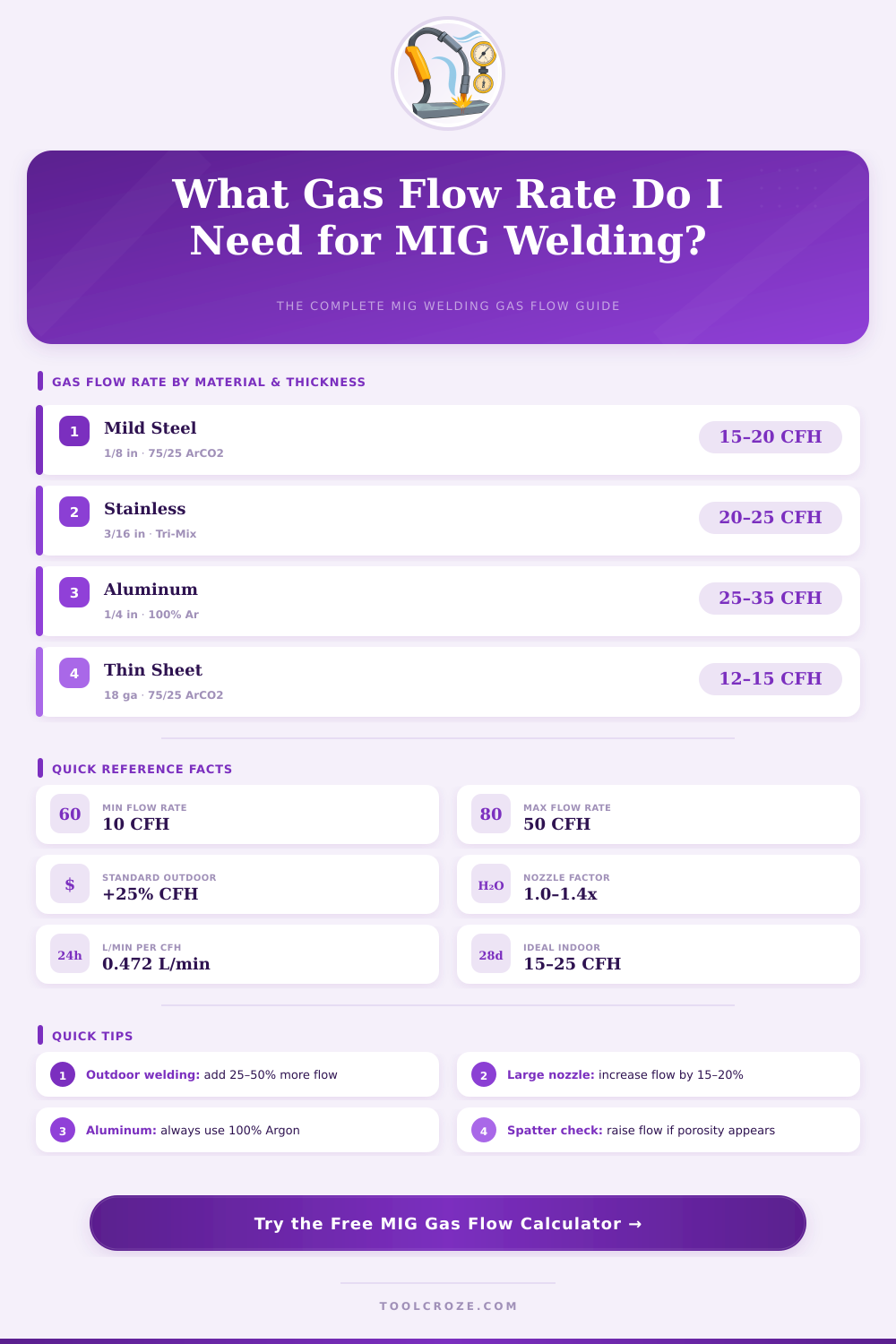
| Material | Transfer Mode | Recommended Gas | CFH Range | L/min Range |
|---|---|---|---|---|
| Mild Steel | Short-Circuit | 75/25 Ar/CO2 | 15–20 | 7–9.4 |
| Mild Steel | Spray Arc | 90/10 Ar/CO2 | 20–25 | 9.4–12 |
| Mild Steel | Globular | 75/25 Ar/CO2 | 18–22 | 8.5–10 |
| Mild Steel | Pulse MIG | 90/10 Ar/CO2 | 20–28 | 9.4–13 |
| Stainless Steel | Short-Circuit | Tri-Mix | 20–25 | 9.4–12 |
| Stainless Steel | Spray Arc | Tri-Mix | 22–30 | 10–14 |
| Aluminum | Spray Arc | 100% Argon | 25–35 | 12–16.5 |
| Aluminum | Pulse MIG | 100% Argon | 30–40 | 14–19 |
| Flux Core | Short-Circuit | 75/25 Ar/CO2 | 12–18 | 5.7–8.5 |
| Silicon Bronze | Short-Circuit | 100% Argon | 15–20 | 7–9.4 |
| Nozzle Size | Diameter (in) | Diameter (mm) | Min CFH | Max CFH | Min L/min | Max L/min |
|---|---|---|---|---|---|---|
| Small | 3/8 in | 9.5 mm | 10 | 18 | 4.7 | 8.5 |
| Standard | 1/2 in | 12.7 mm | 15 | 25 | 7.1 | 11.8 |
| Large | 5/8 in | 15.9 mm | 20 | 35 | 9.4 | 16.5 |
| X-Large | 3/4 in | 19.0 mm | 25 | 50 | 11.8 | 23.6 |
| Environment | Wind Speed | Flow Multiplier | Example: 20 CFH becomes | Recommendation |
|---|---|---|---|---|
| Indoor / Still | 0 mph | 1.00x | 20 CFH | Standard setup |
| Light Draft | 1–5 mph | 1.25x | 25 CFH | Check seals |
| Moderate Wind | 5–10 mph | 1.50x | 30 CFH | Use wind screen |
| Outdoor / Windy | >10 mph | 1.75x | 35 CFH | Welding tent or stop |
| Wire Dia (in) | Wire Dia (mm) | Base Flow (CFH) | Base Flow (L/min) | Typical Amperage |
|---|---|---|---|---|
| 0.023 in | 0.6 mm | 10–15 | 4.7–7.1 | 30–90 A |
| 0.030 in | 0.8 mm | 15–20 | 7.1–9.4 | 50–150 A |
| 0.035 in | 0.9 mm | 18–25 | 8.5–11.8 | 75–200 A |
| 0.045 in | 1.1 mm | 22–30 | 10.4–14.2 | 150–300 A |
| 0.047 in | 1.2 mm | 22–30 | 10.4–14.2 | 150–350 A |
| 0.062 in | 1.6 mm | 30–45 | 14.2–21.2 | 250–500 A |
Porosity is a defect in a MIG weld where there are small hole within the weld metal. Porosity forms when air, oxygen, and nitrogen enter the weld puddle during the welding process. The best way to prevent porosity caused by air entering the weld puddle is to ensure that the shielding gas flows is correct.
If the flow rate of the shielding gas are too low, air will enter the weld puddle because the shielding gas cannot cover the weld puddle. However, if the flow rate of the shielding gas is too high, the shielding gas will create turbulence that will pull air into the weld puddle. Maintaining the correct flow rate of the shielding gas will prevent porosity in the weld metal and ensure that the weld is strongly.
How to Set Shielding Gas Flow for MIG Welding
Shielding gas acts as a protective layer over the weld puddle. The shielding gas protect the weld puddle from oxygen, nitrogen, and other contaminants that will react with the superheated weld metal. Argon, carbon dioxide, and helium gases has different rates of displacing air from the weld puddle due to the different densities of these gases.
The flow rate of the shielding gas is measured in cubic feet per hour (CFH) for the United States or in liters per minute (LPM) for the rest of the world. You must match the shielding gas flow to the welding job to accommodate the metal type, thicknesses, and environments for welding. For instance, welding thin metals indoors will require a different flow rate of shielding gas than welding thick metal outdoors.
The type of metal that you use as the base metal determines the type of shielding gas that you use for welding. For instance, if you are welding mild steel, you will use a mixture of 75% argon gas and 25% carbon dioxide gas. Stainless steel require a type of shielding gas that is a mixture of three different gases for the weld metal.
If you are welding aluminum metal, you will use pure argon shielding gas to weld the aluminum metal because argon gas will prevent the formation of oxide in the weld metal that will make the weld brittle and black. The shielding gas that is correct for welding steel will not necessarily be correct for welding aluminum metal. Using the wrong type of shielding gas will prevent the shielding gas from protecting the metal from reaction with the air, and this will cause the metal to have lack of fusion or cracking in the weld metal.
The type of transfer mode that you use for welding will also have an impact on the required flow rate of the shielding gas. If you are using short-circuit transfer mode, the shielding gas flow will be different than if you used spray transfer mode. If you are welding using pulse MIG transfer mode, the shielding gas flow will be in between short-circuit and spray transfer modes.
Each of these transfer mode will produce a different arc length and droplet action in the weld metal, therefore altering the shielding gas flow requirement for each type of welding mode. The size of the welding nozzle will also alter the shielding gas flow. The welding nozzle is the brass component on the welding gun tip.
A standard nozzle size of a half-inch can handle a shielding gas flow between 15 and 25 CFH. A larger nozzle of 5/8-inch can handle a shielding gas flow of 35 CFH. Using a welding nozzle that is too small for the shielding gas flow will create backpressure that will choke the flow of the shielding gas.
Using a nozzle that is too large for the shielding gas flow will create problem in strong winds because the shielding gas will not be able to maintain it’s shield over the weld metal. Using the correct size welding nozzle for your shielding gas flow will prevent waste of the shielding gas and ensure that it fully cover the weld puddle. The welding environment will also have an impact on the shielding gas flow rate.
Welding in indoor environments with still air requires shielding gas flow rates of 15 to 25 CFH. However, if you are welding outdoors, you will have to increase the flow rate of the shielding gas to combat the wind that will move the shielding gas away from the weld metal. If it is a light breeze, you can increase the flow rate by 25 percent.
If the wind is moderate, you will have to double the shielding gas flow rate to 30 CFH. However, the flow rate should not go above 50 CFH because flow rates above 50 CFH will create a chaotic flow of shielding gas that will pull air into the weld metal. Therefore, weld outdoors in screens or welding tent if the welding environment is exposed to the wind.
The welding wire diameter impacts the shielding gas flow. Thicker welding wire will require more shielding gas than thinner welding wire. This is due to the fact that thicker welding wire will create more heat during the welding process.
Using welding wire that is too thin for the thickness of the base metal will also create issue with the shielding gas flow because thin welding wire will run at lower amperage than thick wire. Additionally, the distance between the contact tip of the welding gun to the workpiece will also impact the shielding gas flow rate. A longer distance between these two points will require a higher flow of shielding gas to ensure that it reaches the arc between the welding metal.
There are some mistake that you should avoid when welding with MIG welding technology. One of the most common mistakes is using your hearing to determine if the shielding gas flow is correct. Many welders may think that if the shielding gas is hissing out of the welding gun, the flow rate is correct.
This is not true because flow meters will not be accurate in measuring the correct flow of shielding gas, and sound cannot be used to determine the shielding gas flow rate. You can use a test to determine if the shielding gas flow rate is correct. First, lay a weld bead on a piece of scrap metal.
Once you create the weld bead, grind and etch the weld metal. If there are dark spots on the weld metal under magnification, these spots are porosity in the weld metal, indicating that the shielding gas flow rate is not correct. Excessive spatter on the weld metal indicates that the shielding gas flow rate is too high.
If there are no porosity spot on the weld metal, the shielding gas flow rate is correct. You can establish the formula to determine the shielding gas flow by multiplying the diameter of the welding nozzle by 25 or 30. For instance, if the welding nozzle is a half-inch in diameter, the flow rate will start at 12.5 to 15 CFH.
However, you will have to add shielding gas to account for the type of metal you are welding, the wind, and the wire diameter. You can start with a preset flow rate for your job. Calculate the requirement of the shielding gas flow based on the variable described above.
After laying a weld bead on a piece of scrap metal, you can adjust the flow meter by one or two CFH units. If the weld metal contains porosity, increase the shielding gas flow rate. However, if the weld metal has turbulence in the weld metal, you should decrease the shielding gas flow rate.