🔧 Go/No Go Gauge Tolerance Calculator
Calculate precise go and no go gauge limits for shaft & hole inspection per ISO/ANSI standards
| IT Grade | 1–3 mm | 3–6 mm | 6–10 mm | 10–18 mm | 18–30 mm | 30–50 mm | 50–80 mm | 80–120 mm |
|---|---|---|---|---|---|---|---|---|
| IT5 | 4 | 5 | 6 | 8 | 9 | 11 | 13 | 15 |
| IT6 | 6 | 8 | 9 | 11 | 13 | 16 | 19 | 22 |
| IT7 | 10 | 12 | 15 | 18 | 21 | 25 | 30 | 35 |
| IT8 | 14 | 18 | 22 | 27 | 33 | 39 | 46 | 54 |
| IT9 | 25 | 30 | 36 | 43 | 52 | 62 | 74 | 87 |
| IT10 | 40 | 48 | 58 | 70 | 84 | 100 | 120 | 140 |
| IT11 | 60 | 75 | 90 | 110 | 130 | 160 | 190 | 220 |
| Symbol | Deviation Type | Upper Dev (es) | Fit Category | Typical Use |
|---|---|---|---|---|
| f6 | Upper (es) | –20 µm | Clearance | Running/sliding fits |
| f7 | Upper (es) | –20 µm | Clearance | Easy running fits |
| g6 | Upper (es) | –7 µm | Clearance | Close running fits |
| h6 | Upper (es) | 0 µm | Transition | Snug push fits |
| js6 | Symmetric | +IT/2 | Transition | Location fits |
| k6 | Lower (ei) | +2 µm | Transition | Light interference |
| n6 | Lower (ei) | +15 µm | Interference | Press fits |
| p6 | Lower (ei) | +22 µm | Interference | Force fits |
| IT Grade | Typical Tolerance (µm) 25mm | 10% Gauge Tol (µm) | Gauge IT Grade | Go Gauge Wear Limit |
|---|---|---|---|---|
| IT6 | 13 | 1.3 | IT3 | 0.65 µm inward |
| IT7 | 21 | 2.1 | IT4 | 1.05 µm inward |
| IT8 | 33 | 3.3 | IT5 | 1.65 µm inward |
| IT9 | 52 | 5.2 | IT6 | 2.6 µm inward |
| IT10 | 84 | 8.4 | IT6 | 4.2 µm inward |
| IT11 | 130 | 13.0 | IT7 | 6.5 µm inward |
Grinding/Honing
Reaming/Boring
Turning/Milling
Rough Machining
of Part Tol
of Part Tol
Start Point
Start Point
Go/no go gauges is used to inspect whether a manufactured part pass or fails according to the tolerance specifications that are set for that part. These gauges can be of many type, such as plug gauges to measure hole and ring gauges to measure shafts. Furthermore, go/no go gauges allow for only two outcome to the inspection: the part passes or the part fails.
A go/no go gauge inspects the boundary of the tolerance zone of the part to be measured. A go/no go gauge consist of two parts: a go gauge and a no go gauge. People use these gauges to ensure that the part meet the required dimensions.
How go/no go gauges work
For holes, the go gauge must pass through the hole if the hole measurements is within the minimum size requirement for that hole. For the same hole, the no go gauge must not pass through the hole if the size of the hole is beyond the maximum limit of that hole size specification. Therefore, the go and no go gauge ensure that the part falls within the upper and lower limit of the tolerance specification.
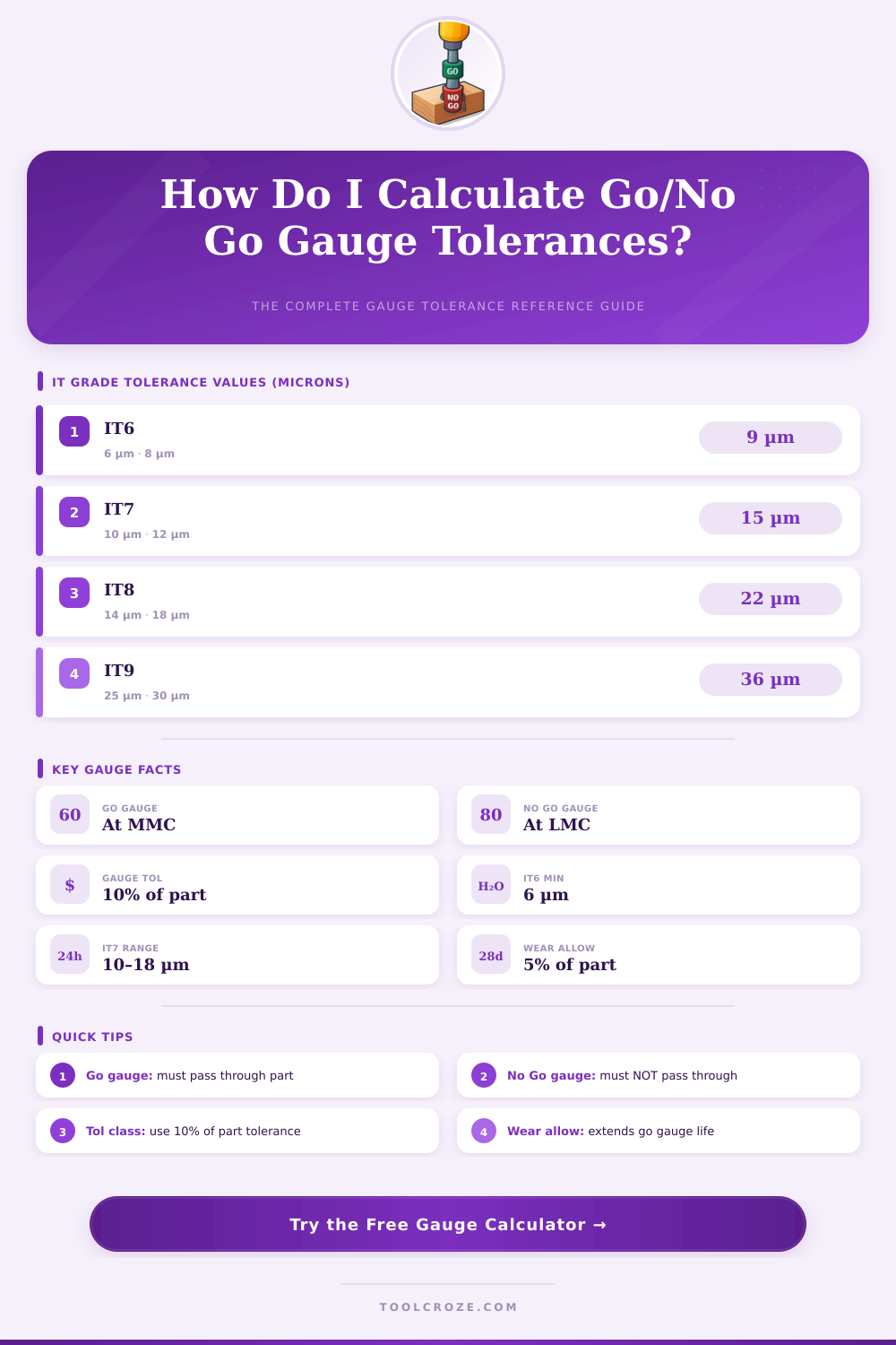
The gauges have tolerances within them, as well. These gauge tolerance must be managed for the quality of the manufactured parts. According to BS 969 standards, gauge tolerances are 10% of the tolerance of the part to be measured.
Additionally, an wear allowance must be provided for these gauges since they will wear down during the measuring process of manufactured parts. If a person ignores the wear allowance of these gauges, the manufacturing company may have to ship defective part or pass parts that do not meet the specifications of the manufactured products. The International Organization for Standardization (ISO) 286-1 standards determine the tolerance class of manufactured parts.
These tolerance classes has an international tolerance (IT) grade associated with them, which is based on the size of the part. For instance, an H7 hole with a 25mm diameter have a tolerance of 21 microns. This means that the size of the hole can be at most 0.021mm larger then the size of the part specification.
For shafts, there are deviation in the size of the shaft that determine whether it will have a clearance fit or an interference fit with another part. A person need to understand the difference between the limits of the part and the limits of the gauge. The limits of the gauge are slightly different than the limits of the part.
For instance, the gauge maker will give the go gauge a tolerance in the plus direction. This is to ensure that it will accept manufactured parts within the tolerance of that part. Furthermore, the go gauge will have an allowance for wear in the go limit so that parts can wear down over time.
The no go gauge will not have an allowance for wear since it is meant to reject parts within the tolerance limits. For high-volume manufacturing plant, such as the automobile industry, many people will use IT7 or IT8 tolerance classes for manufactured parts. These classes are used for their cost-effective implementation into the manufacturing process.
For tighter tolerances, such as IT6, grinding or honing process must be used for the manufactured parts. Furthermore, if a person decides to use carbide gauges for these parts, they will be able to resist the wear that can happen from the tighter tolerance specifications. The wear allowance of a go/no go gauge is a crucial component to provide for accuracy of the gauge.
According to industry standards, the wear allowance will be 5% of the tolerance of the part being manufacture. Furthermore, the go gauge will apply this wear allowance since the go gauge will wear down more then the no go gauge in the manufacturing plant. There are several common error when using go/no gauges.
For instance, people often ignore the size range of different tolerances as specified in the IT tables. Additionally, people will mix metric and imperial unit without properly converting one unit to another. Finally, people will not override the auto-calculated tolerance unless they are matching a legacy drawing of the part.
Go/no go gauges are extremely effective for 100% inspection of manufactured parts. For instance, if a process is required to be fast, go/no go gauges will be beneficial in determining whether a manufactured part passes or fails quality control. These gauges may be used in place of Coordinate Measuring Machines (CMMs) for parts that are not as critical to function.
However, a go/no go gauge will require calibration with master setting ring to maintain it’s accuracy.