4 Leg Wire Rope Sling Calculator
Estimate a four-leg wire rope bridle from load weight, active legs, sling angle, vertical WLL, wire rope diameter and class, bridle geometry, CG offset, D/d bend factor, termination factor, and safety margin.
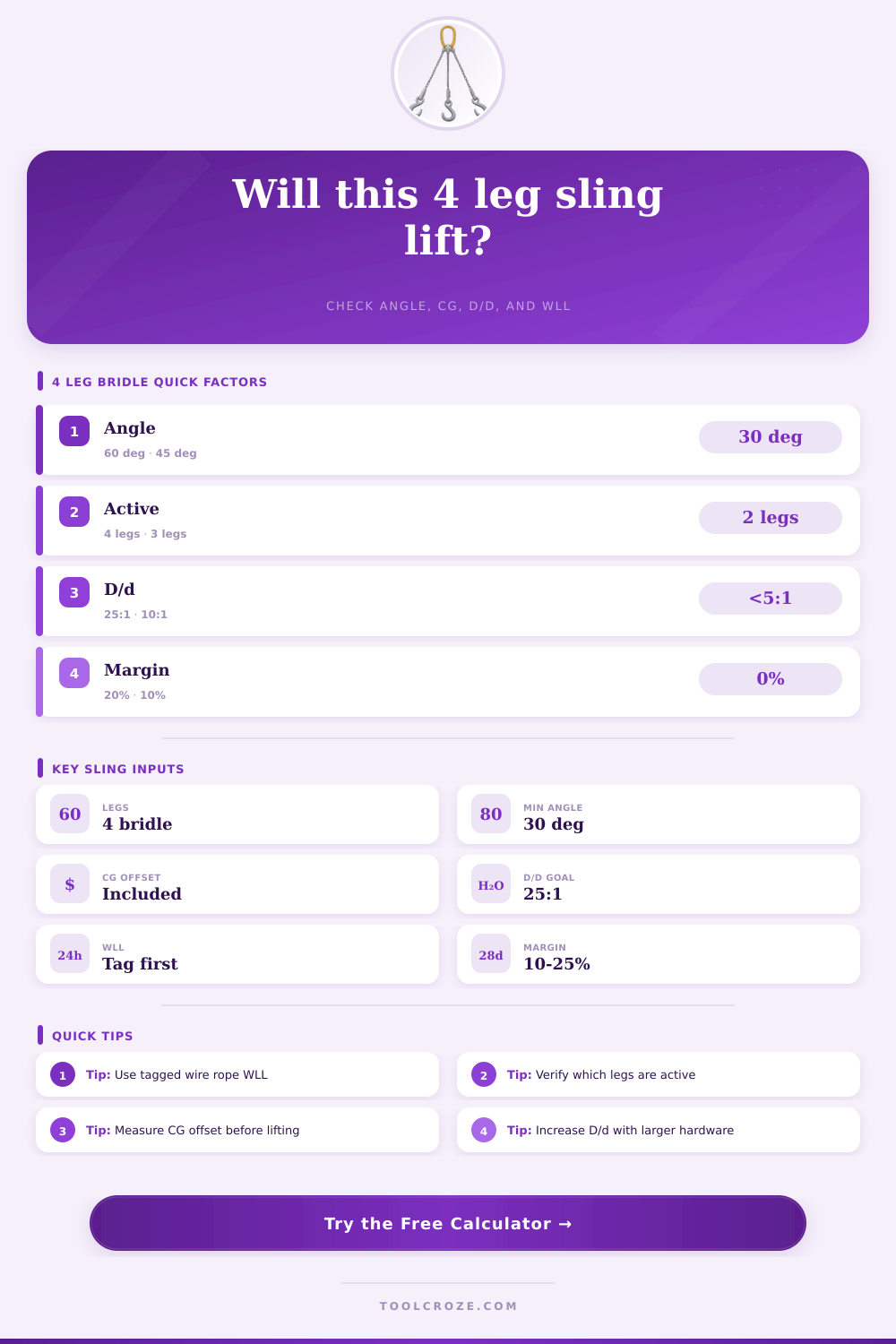
⚙4-Leg Wire Rope Presets
📏Lift Inputs
🧱Wire Rope / Spec Comparison Grid
📊Sling Angle Reference
| Angle from horizontal | Vertical capacity factor | Tension factor | 4-leg planning note |
|---|---|---|---|
| 90° | 1.000 | 1.00 times vertical share | Lowest tension, rarely the actual bridle geometry |
| 75° | 0.966 | 1.04 times vertical share | Excellent angle when headroom allows |
| 60° | 0.866 | 1.15 times vertical share | Common minimum target for routine bridle lifts |
| 45° | 0.707 | 1.41 times vertical share | Capacity and horizontal forces need close review |
| 30° | 0.500 | 2.00 times vertical share | Avoid unless a qualified lift plan specifically approves it |
📐D/d Bend Ratio Reference
| D/d ratio at rope contact | Planning factor | Typical condition | Action |
|---|---|---|---|
| 25:1 or larger | 1.00 | Large pin, shackle bow, or broad saddle | Preferred, still verify manufacturer chart |
| 20:1 to 24:1 | 0.95 | Good radius with small efficiency loss | Check rope construction and fitting limits |
| 10:1 to 19:1 | 0.85 | Moderate bend on pin or load lug | Derate and consider larger hardware |
| 5:1 to 9:1 | 0.75 | Tight hook bowl or small lug contact | High caution; local damage risk rises |
| Under 5:1 | 0.50 to 0.65 | Severe bend or undersized bearing point | Usually needs different hardware or rigging |
🔗Active Legs and CG Offset Reference
| Assumption | Calculator treatment | When it may fit | Risk to check |
|---|---|---|---|
| 4 active legs | All four corner shares counted | Equalized bridle, stiff geometry, verified leg length | One short leg can take more load than expected |
| 3 active legs | Lightest corner omitted, remaining shares normalized | Conservative four-leg bridle planning | CG offset may overload one of the active legs |
| 2 active legs | Two highest-share corners carry the load | Emergency review or severe imbalance screen | Often requires redesign, not a routine lift basis |
| CG offset | Rectangular reaction model from span and offset | Known pick-point rectangle and measured CG | Flexible loads and unequal sling stretch change share |
🛠Wire Rope Construction and Termination Factors
| Spec item | Planning factor | Why it matters | Use with caution |
|---|---|---|---|
| 6x19 IWRC | 1.00 | Baseline for many tagged wire rope slings | Do not exceed tag even when geometry looks favorable |
| 6x36 IWRC | 0.95 | Flexible rope may need bend and abrasion attention | Confirm actual tagged WLL by manufacturer |
| 7x19 cable style | 0.90 | Useful planning derate for lighter cable assemblies | Not a substitute for a rated sling tag |
| Rotation-resistant class | 0.85 to 0.95 | Construction has special handling and termination limits | Side loading, choking, and shock can be restricted |
| Termination basis | 0.80 to 1.00 | End fittings govern actual sling WLL | Tagged WLL should already include fitting efficiency |
💡Rigging Calculation Tips
A four-leg wire rope bridle may be used when a load require the stable support of four legs, and a four-leg wire rope bridle is used when a lift allows for four pick points. A four-leg wire rope bridle system may appear to be simple, but the math behind a four-leg wire rope bridle must take into consideration the angles of the lift, the center of gravity of the load, and the loss of strength in the wire rope when it is bent around an pin. These mathematical functions can be performed for you using the calculator when you input the values for your specific lifting scenario.
Four legs does not necessarily provide four equally share of the load to be lifted. If the load has even a small offset in relation to the center of gravity, one corner of the four-leg wire rope bridle can be required to lift significantly more weight than the theoretical quarter of the total load. The calculator can determine the location of the center of gravity in relation to the rectangle form by the pick points, and then calculates each of the shares of the total load for each leg of the sling.
How to calculate loads for a four-leg wire rope bridle
The leg with the highest share of the total load indicate whether or not the load is balanced. The angle of each sling have a major impact upon the strength of each leg of the sling. As the angle of the sling decreases from horizontal, the tension in each leg of the sling increases.
At sixty degrees the tension values are manageable for many lifting operations, but at forty-five degrees the tension in each leg increase. At thirty degrees the tension increases to the point where changes to the lift geometry are often made instead of attempting to use heavy wire rope to manage the increased load. The sine of the angle of the sling can be entered into the calculator so that the tension in each leg is accurately calculate.
The bend ratio of the wire rope creates a reduction in the strength of the wire rope. As the diameter of the object upon which the wire rope is bent (D) relates to the diameter of the wire rope (d), the strength of the wire rope can be represented. When the D:d ratio is around twenty-five-to-one the strength of the wire rope is nearly equal to the rating of the wire rope.
When the ratio drop to ten-to-one or less, the strength of the wire rope is significantly reduced. The calculator incorporates this ratio into the calculation so that the user can see the capacity of the wire rope. The type of termination of the wire rope and the construction of the rope will also impact the strength of the sling.
If the sling is a tagged sling the efficiency of the fittings is already account for in the strength of the sling. However, if the termination is a hand-tucked splice or wedge socket the strength of the sling will be less than if it were tagged. Similarly, six-by-nineteen or nineteen-by-seven rotation-resistant rope will have different factors in its strength than three-by-three rope.
Such variations can be accounted for in the calculator to reflect the difference in sling strength. In some cases not all legs of a four-leg wire rope bridle will be active legs. If the corner of the load is too short to allow for the attachment of the sling, or if the load is too stiff to allow for the sagging of the sling to each leg, only three active leg may be used in the calculation.
A three-leg calculation is the most common scenario, though using two active legs can be used as an emergency screen to determine if the sling will be strong enough. When using two active legs the calculator will indicate that a redesign of the lift are necessary. The strength of each leg calculated by the calculator is a theoretical value; a safety margin should of been incorporated into the equation.
Many lifting operations apply a safety margin of fifteen or twenty percent to the calculated value. This safety margin account for inevitable error in the lifting operation and allows for the strength of each leg of the sling to be accounted for by the worker. A safety margin is applied after the other calculations are performed and the strength of each leg is indicated.
The calculator does not take into consideration other hardware to be used in the lift. The limitations of shackles, master links, spreader beams, and cranes must also be considered. It is possible for the four-leg wire rope bridle to be of the appropriate strength, but another component of the lifting operation to become a weak link.
Thus, the output of the calculator should be one of many check that are performed on a lifting operation. Common errors in lifting operations include measuring the outside dimension of a skid rather than the dimension of the rectangle formed by the pick points. Second, the diameter of the rope is often measured from the tag of the rope rather than measuring the working load limit of the rope once it has been terminated.
Third, many people do not consider the impact of low angle on the strength of the sling. Errors in any of these component could be caught if the calculations were performed before the lifting of the load. The tables included at the bottom of the calculator are used to provide information regarding each of the variable described in the calculator.
The angle factors, D:d ratios, and active legs can be viewed in these tables so that each user can understand the impact that each of these parameter can have upon the calculation of the strength of each leg of the sling. These tables allow the reader to quickly review the calculations that are made by the calculator. The calculator provides a clear understanding of which factor is having the most impact upon the strength of the sling.
If the sling is weak due to the angle of the sling, the center of gravity of the load, or the bend ratio of the wire rope upon a small pin, the strength of the sling can be increased by altering any of these variable. Thus, the calculator provides an understanding of the limit of the sling, and allows the workers to ensure that the actual lifting operation exist within the limits calculated.