🔧 Hydraulic Cylinder Displacement Calculator
Calculate bore area, rod area, extend & retract volumes, flow rate, and cycle time for any hydraulic cylinder — imperial & metric
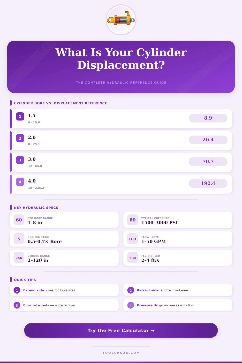
| Bore Dia (in) | Bore Area (in²) | Bore Dia (mm) | Bore Area (cm²) | Max Force @ 2500 PSI (lbf) | Max Force @ 3000 PSI (lbf) |
|---|---|---|---|---|---|
| 1.00 | 0.785 | 25.4 | 5.07 | 1,963 | 2,356 |
| 1.50 | 1.767 | 38.1 | 11.40 | 4,418 | 5,301 |
| 2.00 | 3.142 | 50.8 | 20.27 | 7,854 | 9,425 |
| 2.50 | 4.909 | 63.5 | 31.67 | 12,272 | 14,726 |
| 3.00 | 7.069 | 76.2 | 45.60 | 17,671 | 21,206 |
| 3.50 | 9.621 | 88.9 | 62.07 | 24,053 | 28,864 |
| 4.00 | 12.566 | 101.6 | 81.07 | 31,416 | 37,699 |
| 5.00 | 19.635 | 127.0 | 126.68 | 49,087 | 58,905 |
| 6.00 | 28.274 | 152.4 | 182.41 | 70,686 | 84,823 |
| 8.00 | 50.265 | 203.2 | 324.29 | 125,664 | 150,796 |
| Bore (in) | Flow 2 GPM → Speed | Flow 5 GPM → Speed | Flow 10 GPM → Speed | Flow 20 GPM → Speed | Max Rec. Speed |
|---|---|---|---|---|---|
| 1.5" | 17.0 in/s | 42.4 in/s | 84.8 in/s | — | 24 in/s |
| 2.0" | 9.5 in/s | 23.8 in/s | 47.7 in/s | — | 24 in/s |
| 2.5" | 6.1 in/s | 15.2 in/s | 30.5 in/s | — | 24 in/s |
| 3.0" | 4.2 in/s | 10.6 in/s | 21.2 in/s | 42.3 in/s | 24 in/s |
| 4.0" | 2.4 in/s | 5.9 in/s | 11.9 in/s | 23.7 in/s | 24 in/s |
| 5.0" | 1.5 in/s | 3.8 in/s | 7.6 in/s | 15.2 in/s | 20 in/s |
| 6.0" | 1.1 in/s | 2.6 in/s | 5.3 in/s | 10.6 in/s | 16 in/s |
| Bore (in) | Std Rod Dia (in) | Alt Rod Dia (in) | Rod Ratio | Retract Area (in²) | Area Ratio (Ext/Ret) |
|---|---|---|---|---|---|
| 1.5" | 0.625" | 1.0" | 0.42 / 0.67 | 1.462 / 0.982 | 1.21 / 1.80 |
| 2.0" | 1.0" | 1.375" | 0.50 / 0.69 | 2.356 / 1.656 | 1.33 / 1.90 |
| 2.5" | 1.375" | 1.75" | 0.55 / 0.70 | 3.425 / 2.510 | 1.43 / 1.96 |
| 3.0" | 1.5" | 2.0" | 0.50 / 0.67 | 5.301 / 3.927 | 1.33 / 1.80 |
| 3.5" | 1.75" | 2.5" | 0.50 / 0.71 | 7.216 / 4.714 | 1.33 / 2.04 |
| 4.0" | 2.0" | 2.5" | 0.50 / 0.63 | 9.425 / 7.660 | 1.33 / 1.64 |
| 5.0" | 2.5" | 3.0" | 0.50 / 0.60 | 14.726 / 12.566 | 1.33 / 1.56 |
| 6.0" | 3.0" | 4.0" | 0.50 / 0.67 | 21.206 / 15.708 | 1.33 / 1.80 |
| Application | Bore x Rod x Stroke (in) | Operating Pressure | Flow Rate | Cycle Time (approx.) |
|---|---|---|---|---|
| Dump Truck Hoist | 5" x 3" x 36" | 2500 PSI | 18 GPM | 8–12 sec |
| Log Splitter | 3.5" x 1.75" x 24" | 2000 PSI | 11 GPM | 5–8 sec |
| Skid Steer Boom | 3" x 1.5" x 18" | 3000 PSI | 14 GPM | 3–5 sec |
| Hydraulic Press | 6" x 3" x 12" | 3000 PSI | 8 GPM | 4–7 sec |
| Snowplow Angle | 2.5" x 1.375" x 10" | 1500 PSI | 4 GPM | 2–3 sec |
| Mini Excavator Arm | 2" x 1" x 16" | 2500 PSI | 6 GPM | 3–5 sec |
| Ag / Farm Lift | 3.5" x 1.75" x 30" | 2200 PSI | 10 GPM | 7–10 sec |
| Tie-Rod (Light) | 1.5" x 0.625" x 8" | 1500 PSI | 2 GPM | 3–5 sec |
Hydraulic shift of roll simply said shows the amount of hydraulic oil that moves inside the roll during one whole cycle. Those tools for measurement help to estimate the speed, with that the roll works. Imagine it as the amount of liquid, that the piston press during one move.
Those codes are well known because they affect the speed and the general impact of the hydraulic device.
How One-Sided Hydraulic Cylinders Work
The roll forms part of a special category. It simply extends. Other rolls have a piston, but this one does not.
Instead, it extends by filling the cane with hydraulic oil. To shorten itself, it depends on outside force, for example gravity or the mass of the load. Like this oil pushes the cane outside, and later something else pulls it inward.
The diameter of the cane acts as the usable surface of the piston in that system.
Those rolls have some clear benefits. They cost little and work well. The internal bark escapes rust, because the roll always stays full of oil.
Even so, there are also downsides. They work only during extent. The force for extent is weaker than that of a two-sided roll of same size.
Compared too two-sided rolls, one has less control, and only a limited set of hydraulic valves works for use with them.
Those rolls show up in various uses and help to move different kinds of machines. For instance, the top of a forklift could carry one two-sided roll. Here there is no exit, but instead a hole through the body, that allows oil to pass from the bottom cap and back.
The bottom section does not truly work as a piston for pressure, it simply helps to guide.
The measurement of shift in those rolls became a complex cause. Two companies managed to create a fresh method, installing cable-based sensor for shift directly in the roll itself. That allows the canes of the piston to no longer need to be deeply drilled by means of a special device, regardless of the stroke length.
Another method applies something called LVDT. The spools rest on the body of the roll, while the core moves together with the cane of the piston. One also can put the LVDT directly in the roll under pressures of 3,000 to 5,000 PSI.
For handling those high pressures, the device is either stamped against pressure or thebody is opened to find it.
Big rolls need more liquid to extend. A mighty pump could give that extra amount, but more practical methods reach the same goal. The hydraulic cylinder volume matches the surface of the piston multiplied by the length of the stroke.
Hydraulic rolls seriously help with the movement in industrial and commercial products, turning the pressure of liquid into linear force and motion.