A UNF 3B thread chart provide information about the measurements of threads with a tight tolerance. The threads that has a tight tolerance have a small gap between the male and female threads. Many fastener use a class 2B tolerance.
This class of tolerance allow for more clearance between the threads to make it easier to assemble the fasteners. However, the UNF 3B thread allow for less clearance between the male and female threads. Because there is less clearance between the two types of threads, the threads will remain lock even if the fastener experience vibration.
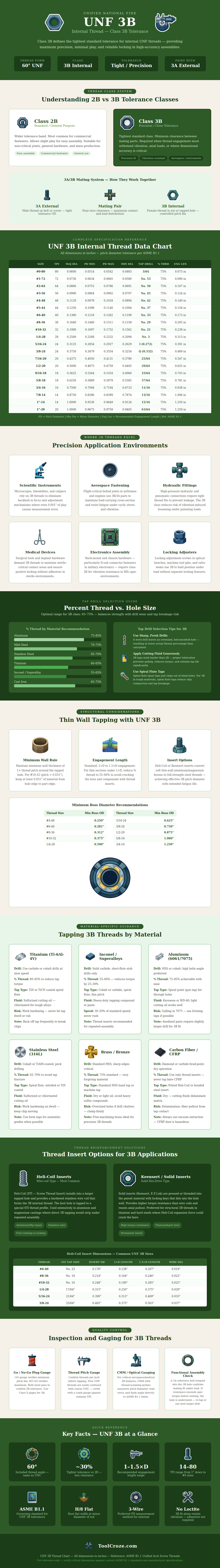
UNF 3B Thread Chart: Tight Fit, Uses and How to Check
Additionally, there is no need to use thread locker or safety wire in these situations because the tight tolerance of the UNF 3B threads prevent them from loosening. The tight tolerance of the UNF 3B thread is due to the pitch diameter of the thread. The chart for UNF 3B threads demonstrate the range of the minimum and maximum pitch diameter of the thread.
The range shown on the thread chart for UNF 3B threads is small. The smaller the range for the pitch diameter, the stiffer the joint that incorporate these threads. Using these types of threads will ensure that the fastener will not drift from it’s position once it is assembled.
The tight tolerance of the UNF 3B thread make it suitable for many application. The tightness of these threads will ensure that they do not move from there place in the machine or device. This movement is not needed with the application of many machine or devices.
For instance, the fasteners on optical instruments or avionics equipment must not allow for the movement of the components. These components must remain in place for the device or machine to function proper. The person that create these types of threads must use the proper size for the tap drill.
The charts for UNF 3B threads recommend that the drill size for these threads will create approximately 75% of the thread. However, the percentage of the thread that is create will change with the type of material that is being drilled. For instance, aluminum metal will allow for a larger drill bit than parts made of stainless steel or titanium because aluminum metal will not work harden during the drilling process.
If the wrong drill bit size is used when tapping these threads, the threads may gall. If the threads gall, then the thread will not be accurate. The person tapping the threads must also consider the wall thickness of the part that is tapped for the UNF 3B threads.
The material around the tapped hole must be thick enough to withstand the torque and the pressure that the tapped fastener will create. If the part that has the UNF 3B tapped threads has too thin of a wall, the part may crack or the threads may distort. Additionally, if the wall that contain the tapped threads is too thin, an thread insert can be used.
The insert will restore the geometry of the UNF 3B threads so that the threads will engage with the appropriate surface. The UNF 3B threads can be inspected using a go plug gauge and a no-go plug gauge. The person will insert the go plug gauge into the threads using only light finger pressure.
Additionally, the no-go plug gauge will be inserted within one turn of the tapped UNF 3B threads. If the go plug gauge easily enter the tapped thread, and the no-go gauge stops within one turn of the threads end, the thread is within the requirement of a class 3B thread. Using these plug gauges will catch any error in the tapping of the threads.
If the UNF 3B threads are not inspected, any errors may not be discover until after the assembly of the machine or device. The main advantage of using UNF 3B threads is that the threads provide consistency. Each joint that is created with these types of threads will behave in the same way each time the joint is assembled.
Because the joint will behave in the same way each time it is assembled, the designer does not need to worry about the preload of the joint for each separate unit. Additionally, because the joint will behave in the same way, the designer can use lighter hardware because the UNF 3B threads will be able to hold the required amount of torque. The UNF 3B thread chart provides the designer with an understanding of the margins of the threads in terms of the type of material that will be used and the thickness of the parts walls.
