Ductwork Offset Calculator
Size a two-elbow duct offset from the required offset distance, fitting angle, duct size, throat allowance, airflow, pressure loss, and available clearance.
⚙HVAC And Fabrication Presets
Choose a typical field condition, then adjust the dimensions to match the measured obstruction and duct route.
📏Offset Geometry And Airflow Inputs
Rectangular uses width and height; round uses diameter.
Lower angles reduce turbulence but require more run.
Measured centerline shift needed to clear the obstacle.
For round duct, enter the outside diameter here.
Use outside duct height including insulation if clearance is tight.
Allowance consumed by each cheek, gore, or elbow throat.
Add S-cleats, drive slips, collars, draw bands, or field trim.
Clear run available along the duct centerline direction.
Used to estimate velocity pressure and two-elbow loss.
Maximum space available across duct height plus offset path.
Extra room for hangers, insulation, access, and minor framing variation.
This modifies the two-elbow loss estimate.
Applied to developed piece length for seams, beads, and trim.
Travel Length
0.0
centerline diagonal lengthSetback / Run Needed
0.0
horizontal advance plus fittingsStraight Connector Cut
0.0
between elbow throatsTwo-Elbow Pressure Loss
0.000
in. w.g. estimated fitting lossAir Velocity
0
FPM through selected ductClearance Status
Check
run and envelope constraints📊Offset / Fitting / Spec Grid
2.00x
travel multiplier for selected angle
1.73x
setback multiplier for selected angle
0.50
two-elbow base k before quality factor
1.00
duct area used for velocity check
📘Reference Tables
| Fitting Angle | Travel Factor | Setback Factor | Fabrication Use |
|---|---|---|---|
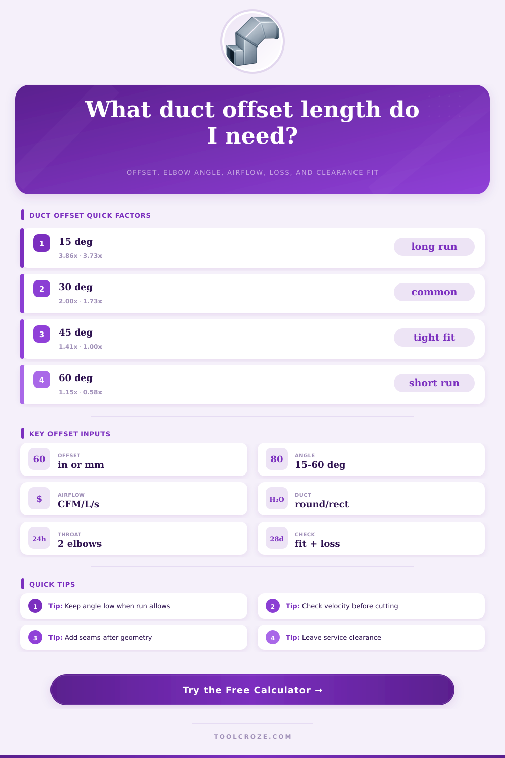
| 15 degrees | Offset x 3.86 | Offset x 3.73 | Longest, smoothest offset when run space is generous. |
| 22.5 degrees | Offset x 2.61 | Offset x 2.41 | Good compromise for low-loss residential trunk adjustments. |
| 30 degrees | Offset x 2.00 | Offset x 1.73 | Common shop layout angle for offsets around joists and beams. |
| 45 degrees | Offset x 1.41 | Offset x 1.00 | Compact and easy to mark, with more fitting loss than 30 degrees. |
| 60 degrees | Offset x 1.15 | Offset x 0.58 | Very short run, usually reserved for tight clearances. |
| Duct Service | Typical Velocity | Offset Concern | Design Note |
|---|---|---|---|
| Quiet supply branch | 500 to 700 FPM | Noise and throw changes | Use low angles and avoid abrupt reducers at the offset. |
| Residential trunk | 700 to 900 FPM | Static pressure stack-up | Compare two-elbow loss with blower external static allowance. |
| Return duct | 400 to 700 FPM | Rumble and grille noise | Keep transitions smooth and preserve filter access clearance. |
| Commercial branch | 900 to 1400 FPM | Balancing and pressure loss | Use vanes, radius elbows, or larger duct when loss is high. |
| Exhaust duct | 1000 to 1800 FPM | Grease, lint, or condensate path | Follow cleanout, slope, and material rules for the system type. |
| Two-Elbow Style | Quality Factor | Best Use | Field Check |
|---|---|---|---|
| Radius elbows or vaned square elbows | 0.90 | Higher airflow or noise-sensitive runs. | Confirm vane spacing, radius clearance, and slip engagement. |
| Standard fabricated elbows | 1.00 | General residential and light commercial offsets. | Check throat length and drive clearance before cutting. |
| Sharp throat or rough field fit | 1.18 | Retrofit work where one side is constrained. | Add balancing margin and inspect for crushed corners. |
| Unvaned mitered elbows | 1.35 | Only when space forces compact fittings. | Expect higher loss, turbulence, and possible noise. |
| Fabrication Check | Rule Of Thumb | Why It Matters | Calculator Input |
|---|---|---|---|
| Throat allowance | 2 to 6 in per elbow | Controls the remaining straight connector length. | Enter the shop or fitting standard throat length. |
| Slip and drive allowance | 1 to 3 in total | Prevents a perfect geometry length from being too short to join. | Enter total connector allowance for both ends. |
| Insulated duct envelope | Duct plus insulation plus reserve | Clearance can fail even when centerline geometry works. | Use outside size and reserve clearance inputs. |
| Seam and trim factor | 5% to 12% | Allows beading, Pittsburgh seams, laps, and field trimming. | Enter fabrication waste and trim percentage. |
💡Layout Tips And Safety
A duct offset occur when the duct must move from one position to another due to an obstacle such as a beam, an joist, or a pipe in the way. Beyond the distance that the duct must move, there are a few additional factor to consider when creating a duct offset. For instance, it is important to consider how much length that the duct offset will use, whether the fittings for the duct will fit into the available space, and whether the pressure loss that occur within the offset will negatively impact the airflow that exits the registers in the rooms.
The distance that the duct must move is referred to as the offset distance. However, the offset distance is not the only measurement for a duct offset. Additionally, you must select the angle of the duct offset.
How to Plan a Duct Offset
For instance, angles that are shallowly to the offset will require the offset to have a longer length, but the air will move more smooth through the offset. In contrast, angles that are steep to the offset will make the length of the offset shorter, but will create turbulence within the offset which may lead to increased noise radiating from the duct. Many duct installers prefers angles of thirty degrees for the offset.
People use angles of thirty degrees because they provide some balance between the length of the duct offset and the space available for that installation. Angles of thirty degrees ensure that the diagonal travel of the duct offset is not too long, the setback of the duct is not too long (as it may take up an entire bay of a joist), and that the pressure loss within the offset is low enough to ensure that the dampers in the duct can function correctly. Angles of forty-five or sixty degrees may be used in instances where space is limited.
However, these angles will increase the static pressure of the offset, which may cause the straight connector to be too short to allow for installation of the joints of the duct offset. The straight connector is the metal that joins two elbows together to form the duct offset. The length of the straight connector must be accounted for in calculating the length of the duct offset.
Each elbow has a certain length known as the “throat” length, which is the portion of the elbow that turns from one position to another. Additionally, the straight connectors has lengths that contribute to the total length of the duct offset. If the diagonal travel of the duct offset is too short, then the straight connector will be too short to permit installation of the joint.
Thus, the length of the duct offset must account for the lengths of both the throats of each elbow and each straight connector prior to cutting the metal panels for installation. Airflow is one of the factors that impact a duct offset. If the air velocity in the duct system is high, then the pressure loss that the offset of the duct causes will be more significant at the register.
A calculator can help to show the pressure loss that a pair of elbows in the duct offset causes. Based off this information, it is possible to decide if a duct of a larger size should be used, or if the angle of the offset should be changed. The amount of space in which the duct system can exist is referred to as the “clearance” of the duct system.
The centerline geometry of the duct offset may be able to fit into the available space for the ducts, but the actual duct (with insulation and hangers) may not fit into that space. It is important to account for the insulation and hangers in the duct system when measuring the available clearance. If the duct offset and insulation is not allowed to come in contact with the obstacle in which it will be installed, then the offset will need to be accounted for in relation to those factor.
Many mistakes are made in installing a duct offset due to the fact that the duct offset is often treated as a simple measurement. People may measure the required distance of the offset, and the angle of that offset, but they may not account for the fact that the straight run of the duct may not be able to accommodate for the required setback of the offset. Additionally, the type of elbow that will be used in the duct offset may be ignored; a radius elbow or vaned square elbow will create different level of pressure loss than a sharp miter elbow, which will impact the performance of the system created by those ducts.
A reference table can help to show the different multipliers for various angles of duct offsets. For instance, using a fifteen degree angle for the offset will create a duct offset that is very long, while using a sixty degree angle will create a very short duct offset. Each of these angles will impact both the length of the duct offset, as well as the performance of that offset.
By plugging the measurements of the duct system into a calculator that applies these factor from the reference table, it is possible to determine if the duct offset will work for the system once the lengths of the throats, connectors, and based on the available clearance is taken into account. By treating the duct offset as a small system that must be installed into the main system, it is possible to create a duct offset that will not interfere with the performance of the overall system. Furthermore, each of these duct offsets will be successful in allowing the registers to provide the expected amount of airflow.
Additionally, because of the offset, it will not be necessary to install an inline booster fan or to rebuild the soffit boxes. By treating each of these aspects of the duct system as a small system that can be mathematically analyzed, it is possible to cut the metal for the system according to the determined angle of the offset and allowances for each component of the system.