Pneumatic Flow Rate Calculator
Estimate valve flow, tubing pressure drop, actuator air demand, cycle rate capacity, and the limiting component in a pneumatic circuit.
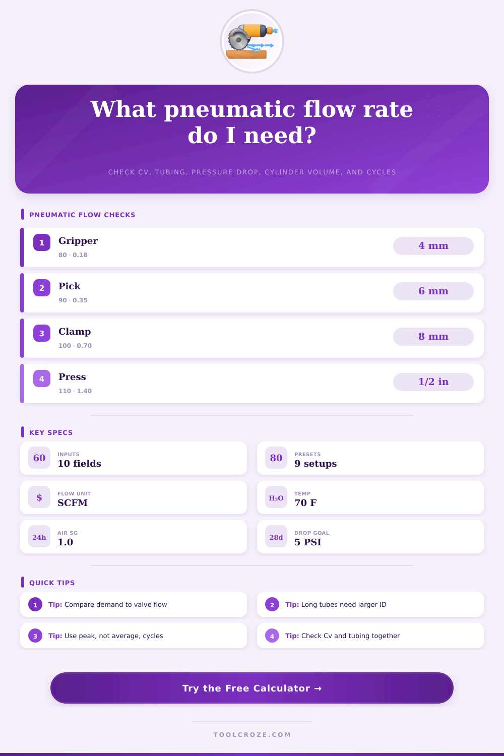
Choose a real pneumatic circuit, then adjust the pressure, Cv, tube ID, length, pressure drop, actuator volume, and cycle rate.
Gauge pressure at the valve inlet or manifold supply.
Pressure loss allowed across the valve and tube during motion.
Use line temperature near the valve after cooling and drying.
Use the Cv for the active flow path, including spool and exhaust style.
The calculation uses inside diameter. Metric tube IDs vary by wall thickness.
Include moving cable carriers, manifold drops, and flexible sections.
Converted to equivalent straight-tube feet for line-drop estimating.
Use cap-end or rod-end volume that must fill during one stroke.
Double-acting cylinders often consume air on both extend and retract.
Use the peak sustained rate, not a slow setup or manual jog rate.
Adds reserve for leakage, speed changes, regulator loss, and simultaneous motion.
Used to compare instantaneous fill flow against average SCFM demand.
Pneumatic Flow Results
Formula Breakdown
Best for grippers, small slides, and short 4 mm or 6 mm tube runs with modest speed.
Common for packaging cylinders, light clamps, and 6 mm tube near the actuator.
Useful for larger bore cylinders, 8 mm tube, and faster extend or retract motion.
Matches presses, lift cylinders, 3/8 in hose, and manifolds with simultaneous motion.
| Valve type | Typical Cv | Approx. SCFM at 90 PSIG, 5 PSI drop | Common pneumatic use |
|---|---|---|---|
| 10 mm miniature solenoid valve | 0.08 to 0.18 | 4 to 10 SCFM | Finger grippers, pilot air, small ejectors |
| 15 mm compact manifold valve | 0.20 to 0.40 | 11 to 22 SCFM | Slides, stops, small double-acting cylinders |
| 18 mm or ISO size 1 valve | 0.55 to 0.85 | 30 to 47 SCFM | Clamps, lifts, mid-size production cylinders |
| ISO size 2 or high-flow body | 1.0 to 1.6 | 55 to 88 SCFM | Press cylinders, shuttle tables, quick exhaust circuits |
| Large poppet or process air valve | 2.0 and higher | 110+ SCFM | Blow-off headers and large air actuators |
| Tube or hose ID | Typical working range | Velocity warning range | Pressure drop note |
|---|---|---|---|
| 4 mm OD class, about 2.5 mm ID | 1 to 6 SCFM | Above 80 fps | Keep short; pressure drop rises sharply on fast cylinders |
| 6 mm OD class, about 4 mm ID | 5 to 18 SCFM | Above 90 fps | Common for compact actuators near valve manifolds |
| 8 mm OD class, about 6 mm ID | 15 to 35 SCFM | Above 100 fps | Good default for clamps, stops, and medium slides |
| 10 to 12 mm tube class | 30 to 70 SCFM | Above 120 fps | Use for longer runs and larger cylinder ports |
| 3/8 in to 1/2 in hose | 45 to 120 SCFM | Above 140 fps | Works for press cylinders, blow-off pulses, and manifolds |
| Actuator example | Approx. volume per stroke | Typical cycle rate | Flow sizing note |
|---|---|---|---|
| 16 mm bore x 50 mm stroke gripper slide | 1.0 to 1.5 in³ | 30 to 120 cycles/min | Valve response and 4 mm tube length often dominate |
| 32 mm bore x 100 mm stroke cylinder | 7 to 9 in³ | 20 to 80 cycles/min | Usually fits compact Cv 0.35 to Cv 0.7 valves |
| 50 mm bore x 150 mm stroke cylinder | 28 to 32 in³ | 10 to 45 cycles/min | Check both extend and retract flow for speed balance |
| 80 mm bore x 200 mm stroke lift cylinder | 95 to 105 in³ | 4 to 20 cycles/min | Needs high Cv, larger tube, and controlled exhaust |
| Air pulse or blow-off nozzle bank | Use nozzle equivalent volume | 5 to 300 pulses/min | Peak pulse flow can be far above average SCFM |
| Condition | Flow effect | Cycle effect | Practical sizing check |
|---|---|---|---|
| Lower supply pressure | Less valve mass flow | Slower cylinder fill | Do not assume a 90 PSI Cv rating at 60 PSI supply |
| Higher pressure drop allowance | More calculated flow | Higher speed possible | Check final actuator force after the pressure loss |
| Hot compressed air | Lower density through valve | More actual volume in tube | Hot lines can need more ID for the same SCFM |
| Cold plant air | Higher density | Condensate risk rises | Dry air and proper draining still matter for valves |
Pneumatic systems may appear to be a simple technology because air enters a system, cylinders perform a function, and a gripper clamp onto an object. However, pneumatic systems are also subject to certain limit in there performance. Many people feel that air is a simple component in the system; however, air is often the bottleneck in a system that is attempting to increase the speed at which the grippers cycle.
The flow rate is one of the most important variable in a pneumatic system design, and many pneumatic system engineers make mistakes when they treat the valve, the tubing, and the cylinder as separate components of a system. However, when they treat them as one moving volume of air within the system, they are more easily sized to meet a system’s requirement. The calculator that is provided on this page brings all of these different component of a pneumatic system into one single calculation.
Find and fix air flow problems in a pneumatic system
By entering information about the supply pressure, the Cv of the pneumatic valve, the inside diameter of the tubing, the length of the pneumatic tubing, the volume of the actuator, the number of strokes per cycle, and the cycle rate of the pneumatic system, the calculator will output information about the actual capacity of the pneumatic valve, the capacity of the tubing at the allowed pressure drop, the average air demand of the system, and the instantaneous air flow rate required to achieve the target stroke time of the system. These outputs will help to show which component of a pneumatic system is holding it back. The calculator can account for the effect of varying the system’s operating pressure and temperature.
Variables such as supply pressure will impact the density of the air that passes through the pneumatic system. If a pneumatic valve is set to allow for 90 PSIG of pressure, for instance, the air mass flow through that valve will drop if the supply pressure drops to 60 PSIG. Similarly, if the air within the system is hotter than ambient air, it is less dense.
Because density is inversely related to volume, if the system utilizes less dense air, it will contain fewer number of molecules passing through the system than if it were using air at a lower temperature. Because these variables can impact the performance of the pneumatic system, they are accounted for within the calculator to ensure the results of the calculation reflect those variables in the actual pneumatic system. The capacity of the tubing within a pneumatic system is another parameter that is sometimes misunderstood.
If a pneumatic system has a large valve but it is connected to a small-diameter tube to the actuator cylinder, the system will not be able to move as much air through that small tubing as the large valve is capable of moving. If the system cannot move that much air through that tubing, the pressure drop in that system will reduce the speed at which the actuator can move. This is one of the reasons that the capacity of the tubing in a pneumatic system is calculated in this calculator.
Not only can the user enter the inside diameter of that tubing into the calculator, but the length of that tubing and the number of fittings in the system can also be accounted for in the calculation. In pneumatic systems, the relationship between actuator volume and cycle rate determines the air demand of the system. A small pneumatic gripper that performs 80 strokes per minute will often require more air than a large pneumatic cylinder that cycles only 20 times per minute.
The calculation of air demand within this calculator first calculates the volume of the pneumatic actuator in standard cubic feet. The calculator multiplies the volume in standard cubic feet by the compression ratio of the pneumatic system at the supply pressure. This result is multiplied by the number of strokes per cycle that the system performs and the number of cycles per minute that the actuator completes.
Finally, an allowance for air loss within the system can be added to this calculation. Air loss can occur due to leaks in the system, droop in the pressure supplied by the regulator for large pneumatic systems, or if other pneumatic actuators are cycling at the same time within the system. Another mistake that individuals who are analyzing a pneumatic system often make is to ignore the difference between average air demand and instantaneous fill rate.
If a pneumatic system calculates that the average demand for air is within the rated specifications of the pneumatic components in the system, the system may still fail to perform at the target stroke time for the pneumatic actuator. This is due to the inability of the components in the system (specifically the valve and the tubing) to deliver the instantaneous flow rate required to achieve the target stroke time. By calculating both the average air demand and the instantaneous air fill rate for a pneumatic system, an engineer can recognize both the possibility of system limitations due to total air volume provided by the air compressor and the air’s rate of arrival at the pneumatic actuator.
In an actual industrial plant site, there are often additional variables that complicate pneumatic systems that cannot be accounted for in this calculator. The supply pressure to the pneumatic system may fluctuate as other machines use the air in the plant. Additionally, the temperature of the air may change from morning shifts to afternoon shifts.
The quality of the air in the system may also deteriorate due to contamination. Such variables are not accounted for in the calculator. The status message that is sent from the calculator is also only a point of departure in analyzing the pneumatic system.
Additional observation of the pneumatic system is required to ensure that the system is actually working as it should to perform the required movement of the object. Many engineers who design pneumatic systems neglect the importance of air demand to the sizing of valves. If a designer focuses on the Cv of the pneumatic valve as the most important specification in the design of a system, a high-Cv valve will fail if it is connected to small-diameter tubing that cannot move that much air to the pneumatic actuator.
The same failure occurs if a modest valve is selected if it is connected to the actuator through relatively long and tubing of adequate diameter. However, if air demand is considered when sizing the components of a pneumatic system, such a mistake is avoided. The same principle applies to altering the cycle rate of a pneumatic system.
Intuition would suggest that if the cycle rate is doubled, the average demand for air will double as well. However, if the cycle rate is doubled, the amount of time that each stroke of the pneumatic actuator takes is halved. This will create an increased demand for instantaneous air flow to achieve those fast stroke rates.
An allowance factor is provided for pneumatic systems that allows for these increases in rate to be accounted for in the system. This allows for the designer to avoid having to guess at the effects that increasing cycle rate will have on the system pressure drop and velocity of the air within that system. After calculating the values of a pneumatic system, it is also possible to alter one of the variables of that system in the calculator.
If the diameter of the tube in a pneumatic system is increased, the amount of air that can move through the system increases. If the length of the pneumatic tubing is shortened, both the pressure drop and the velocity of the air in that system will improve. The allowable drop in pressure in a system can be increased to allow for greater flow through the system, although the force that is delivered by the pneumatic actuator will decrease with a lower supply pressure.
Each of these changes can be tested in the calculator prior to purchasing any pneumatic system components. The goal in designing a pneumatic system is to create a system that moves the object as required while minimizing the number of times the compressor must work to deliver air to that system. Air in a pneumatic system is a compressible gas.
There are friction losses through the tubing. There are flow limitations through the pneumatic valves. The pneumatic actuator has a volume that limits how much air can enter and exit the actuator.
By considering each of these variables in the calculation of the pneumatic system, an engineer can create a better system than if each of those variables was ignored. The calculator is a design that helps to make certain that the next change that is made to a pneumatic system will fix the problem of the system that is currently existing.