Pneumatic Cylinder Lifting Capacity Calculator
Estimate vertical lifting capacity, load margin, return-side capacity, air volume, and stroke energy from bore, rod, pressure, mounting angle, friction, safety factor, stroke, and acceleration allowance.
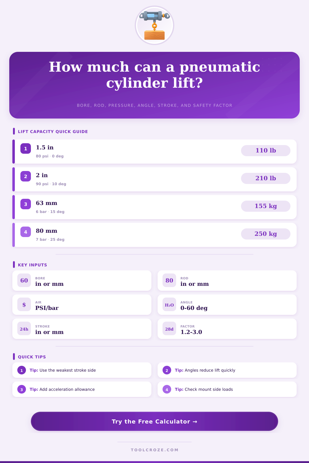
Choose a common industrial lift case, then adjust bore, rod, pressure, angle, stroke, load, friction, and dynamic allowance for your setup.
| Bore size | Area reference | Typical lift at 80 psi | Application note |
|---|---|---|---|
| 1.25 in / 32 mm | 1.23 in² | 65 to 80 lb | Light stops, small guards, gripper lifts |
| 1.5 in / 40 mm | 1.77 in² | 95 to 115 lb | Small doors and vertical product pushers |
| 2 in / 50 mm | 3.14 in² | 165 to 210 lb | General machine lift and fixture elevator use |
| 2.5 in / 63 mm | 4.91 in² | 260 to 325 lb | Lift-assist arms and heavier covers |
| 3.25 in / 80 mm | 8.30 in² | 440 to 550 lb | Higher force, higher air demand, slower valves |
| Mounting angle | Vertical force kept | Capacity effect | Design check |
|---|---|---|---|
| 0 degrees | 100% | Full vertical lift | Best case for simple capacity sizing |
| 15 degrees | 97% | Small reduction | Check pivot clearance and rod alignment |
| 30 degrees | 87% | Noticeable reduction | Side load and guide friction become important |
| 45 degrees | 71% | Large derating | Use geometry at the worst part of travel |
| 60 degrees | 50% | Half force vertical | Usually needs a larger bore or linkage change |
| Lift condition | Friction allowance | Acceleration allowance | Practical note |
|---|---|---|---|
| Clean guided lift | 5% to 12% | 5% to 10% | Slow motion, balanced load, good bearings |
| Vertical slide table | 10% to 20% | 10% to 20% | Common automation default range |
| Pivoting lid or hatch | 12% to 25% | 10% to 30% | Use worst-case angle near start of lift |
| Dirty or side-loaded guide | 25% to 45% | 15% to 35% | Measure drag and consider guided actuator |
| Fast hard-stop motion | 15% to 30% | 30% to 60% | Add shock absorption before raising speed |
| Cylinder or mount type | Best lifting use | Limit to watch | Material/spec cue |
|---|---|---|---|
| Front flange | Straight vertical machine lift | Frame bending at flange | Steel plate support is preferred |
| Rear clevis | Hatches and changing-angle linkages | Pin wear and buckling angle | Use hardened pins and bushings |
| Center trunnion | Balanced pivoting covers | Side loads from offset arms | Align trunnions with load center |
| Guided compact | Short product or fixture elevators | Bearing load and stroke limit | Check moment rating, not just force |
| Rodless slide | Long vertical or inclined travel | Carriage load and brake holding | Use rated guide and holding device |
Pneumatic cylinder are used in many different machines, but pneumatic cylinders are used to complete tasks as varied as moving packaging machine doors or lifting hopper lids. The three main variables that affect the force that a pneumatic cylinder can provide are air pressure, surface area, mounting angles, and friction. If the person who designs the machine does not balance these correctly, then the pneumatic cylinder may stall or overheat its valve.
The bore of the cylinder is the most important variable to consider in determining the force that can be provided by a pneumatic cylinder. A larger cylinder bore will produce more force than a smaller bore, assuming the air pressure are the same. However, larger bores require more air volume to fill the cylinder with air, and larger bores will respond slow to air pressure changes if the air supply line is too small.
Things That Affect a Pneumatic Cylinder’s Force
The diameter of the rod is also important to consider. Because the rod takes up space within the pneumatic cylinder