Pneumatic Cylinder Cycle Time Calculator
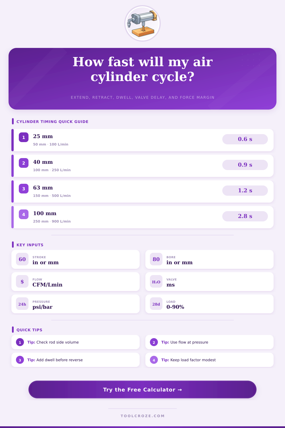
Estimate extend and retract time from cylinder geometry, air flow, valve response, cushion settings, dwell, working pressure, and load factor.
⚙Cylinder Cycle Presets
Pick a realistic actuator setup, then tune the dimensions, flow, valve response, pressure, and load factor to match the machine.
📏Actuator and Valve Inputs
Use the actual travel from retracted to extended position.
Rod diameter reduces retract-side volume and force.
Use estimated delivered flow through fittings, tubing, and speed controls.
Valve delay applies on each direction change; cushion applies at each end of stroke.
Use the programmed wait before the valve shifts back.
Use pressure available at the cylinder while the actuator is moving.
Higher load factor reduces practical speed and force margin.
This adjusts for common valve, tubing, and motion-control losses.
🔧Actuator, Valve, and Spec Comparison Grid
📊Pneumatic Cylinder Reference Tables
| Bore size | Extend area | Typical fast stroke | Where it fits |
|---|---|---|---|
| 20 to 25 mm / 3/4 to 1 in | 0.31 to 0.79 in² | 50 to 150 mm | Sensors, diverters, small pick-and-place slides |
| 32 to 40 mm / 1-1/4 to 1-1/2 in | 1.25 to 1.77 in² | 75 to 200 mm | Clamps, gates, stops, packaging cylinders |
| 50 to 63 mm / 2 to 2-1/2 in | 3.14 to 4.91 in² | 100 to 300 mm | Pushers, presses, guided tooling, ejectors |
| 80 to 100 mm / 3 to 4 in | 7.07 to 12.57 in² | 150 to 500 mm | Heavy lift, transfer, guarded slow motion |
| Valve and porting style | Flow behavior | Response range | Timing note |
|---|---|---|---|
| Compact solenoid valve, small ports | Restricted on larger bores | 25 to 60 ms | Often dominates timing on short strokes. |
| Standard 5/2 valve, matched ports | Balanced for most cylinders | 20 to 45 ms | Good default when tubing is not excessive. |
| High-flow valve with short tubing | Best for rapid fill and exhaust | 15 to 35 ms | Can expose cushion and load limits. |
| Proportional or soft-start motion | Controlled acceleration | 40 to 120 ms | Use when impact or positioning matters more than speed. |
| Load factor | Force margin | Speed effect | Design interpretation |
|---|---|---|---|
| 0% to 25% | Large | Minor | Usually suitable for quick motion and light tooling. |
| 26% to 50% | Moderate | Noticeable | Common working range for reliable automated cycling. |
| 51% to 70% | Small | High | Expect slower starts and more sensitivity to pressure drop. |
| Above 70% | Very small | Severe | Recheck bore, pressure, friction, and mechanical alignment. |
| Application | Common target cycle | Cushion choice | Spec comparison |
|---|---|---|---|
| Pick-and-place slide | 0.4 to 1.0 seconds | Low cushion, external stops | Small bore, high-flow valve, short tubing |
| Workholding clamp | 0.3 to 0.8 seconds | Soft close near part | Force margin matters more than peak speed |
| Carton pusher | 0.8 to 2.0 seconds | Moderate cushion | Rod-side retract flow often sets the cycle rate |
| Guard door actuator | 1.5 to 4.0 seconds | High cushion or flow control | Controlled speed and safety interlocks dominate |
💡Cycle Time Tips
Pneumatic cylinder are used to move an object from one position to another and then move that object back to the original position. The process of moving the object from one position to another and back to the original position is referred to as a cycle. The amount of time it takes for the pneumatic cylinder to complete one cycle is referred to as the cycle time.
The cycle time is important in that it helps to determine if the machine remains on schedule with the schedule that is set for that machine, or if it falls behind of that target rate. One can use a calculator to determine the cycle time of a pneumatic cylinder by entering specific data points regarding that cylinder; entering these data points will allow one to size a new pneumatic cylinder or troubleshoot an existing pneumatic cylinder. The volume of air that is required to move each pneumatic cylinder can be different between the stroke that extends the cylinder and the stroke that rettracts the cylinder from its extended position.
How to Calculate Cycle Time for a Pneumatic Cylinder
Multiplying the area of the cylinder by the length of the stroke of the pneumatic cylinder calculates the volume of air that is required to extend the cylinder. The volume of air that is required for the retract stroke is smaller than the volume required to extend the cylinder, as the rod of the pneumatic cylinder take up some of the volume within the cylinder. Additionally, because the retract stroke will take place at a faster rate than the extend stroke (assuming the same flow rates of air for each stroke), the calculator accounts for these different volumes by calculating each chamber separately.
Thus, if the retract flow is faster than the extend flow, the pneumatic cylinder will reflect that in its calculation. There are three different elements of time that can be utilized in the pneumatic cylinder. Each of these elements can add delay to the movement of the piston within the cylinder.
The first of these elements is valve response time, which introduces a delay after the valve changes but before the air reaches the pneumatic cylinder. The second of these elements is cushioning, which introduces a time delay at each end of the stroke to allow the piston rod to slow and stop. The third of these elements is dwell time, which introduces a delay before the valve is instructed to change direction.
Each of these time elements must be accounted for in calculating the cycle time of the pneumatic cylinder. Another factor in the operation of a pneumatic cylinder is the load factor of the cylinder. The load factor is the percentage of the theoretical force of the pneumatic cylinder that the load that is attached to the pneumatic cylinder uses.
If the load factor is low, then the pneumatic cylinder will have a large amount of force that it can reserve; this allows for the piston to accelerate rapid to the desired position. If the load factor is high, however, it will use up the force of the pneumatic cylinder, and the low force margin will cause the rate of movement of the piston to decrease. The pneumatic cylinder calculator displays the load margin as a percentage to allow operators to read the force with which the pneumatic cylinder will move.
The last of the factors that can influence pneumatic cylinders are the effects of pressure. Pressure affects the force that is created by the pneumatic cylinder, as well as the flow of the air within the cylinder. Higher levels of pressure will allow for more air to travel through the orifice in a given amount of time.
However, increased pressure will also increase the compression ratio of the pneumatic cylinder. Increased compression ratios will lead to increased consumption of free air by the pneumatic cylinder. Thus, the pneumatic cylinder calculator adjusts the flow based upon the pressure that is selected, and then recalculates the time for each stroke of the piston based upon that adjusted flow.
In the real world, pneumatic cylinders will often differ from the conditions within the tested pneumatic cylinders. For instance, any tubing will add to the volume of the system, and any elbows or quick-connect fittings will introduce resistance into the airflow. Additionally, any speed controls or mufflers will restrict the amount of exhaust air that can leave the pneumatic cylinder; restricted exhaust air will make the retract stroke take longer than the extend stroke of the pneumatic cylinder.
To account for these differences, it is important to enter the actual flow rate that the pneumatic cylinder will use into the calculator, rather than the Cv of the valve that the pneumatic cylinder will utilize. Within the pneumatic cylinder manufacturer’s manual, there are often reference tables that detail the different bore sizes for the pneumatic cylinder and the lengths of strokes that the pneumatic cylinder may have; each of these tables also contain information regarding which types of valves are best suited to each size of pneumatic cylinder. Each of these tables are not rules that must be followed in the installation of the pneumatic cylinder.
However, they do help to ensure that the pneumatic cylinder and its components are installed in a way that will avoid introducing potential mismatches between the size of the cylinder and the valves that the pneumatic cylinder utilizes. For instance, the tables may indicate that large bore sizes of the pneumatic cylinder should not be paired with compact valves. Another way of gaining additional information about the pneumatic cylinder is to calculate the time that the pneumatic cylinder will take to complete its cycle with and without introducing the time elements of cushioning and dwell time.
By calculating the cycle time without these variables, one can compare the time for each stroke to the actual cycle time of the pneumatic cylinder. By determining the difference between these two values, it is possible to decide whether the settings for the pneumatic cylinder should be adjusted. It is also important to compare the extend time to the retract time for the pneumatic cylinder.
If the extend time is longer than the retract time, or if the retract time is longer than the extend time, it may be beneficial to improve the flow within that cylinder; improving the flow may include changing the size of the ports through which air flows to the pneumatic cylinder, or the size of the exhaust ports of the pneumatic cylinder. Different lengths of stroke that the pneumatic cylinder will travel will impact the cycle time in different ways. For instance, if the stroke is short, factors like valve response time and cushioning will be the primary elements that impact the cycle time; if the stroke is long, however, the flow of the air within the system will be the primary impact on the cycle time of the pneumatic cylinder.
Additionally, if the load that is attached to the pneumatic cylinder is heavy, the force margin of that pneumatic cylinder will be reduced, leading to an increase in the cycle time. The pneumatic cylinder calculator displays these relationships between the stroke length, load, force, and cycle time for the operator. Finally, the goal of incorporating a pneumatic cylinder into a machine is to enable that machine to have a reliable cycle time.
A reliable cycle time will have some extra time to account for potential changes in the pressure within the pneumatic cylinder, the temperature of the pneumatic cylinder, and the wear of the components of the pneumatic cylinder over time. Thus, knowing the cycle time will allow the operator to decide if the pneumatic cylinder is currently sufficient to meet the requirements of the machine, or if it may need to be changed. The pneumatic cylinder calculator removes the need for the operator to perform any arithmetic calculations to the pneumatic cylinder.