Pneumatic Cylinder Pressure Calculator
Estimate extend and retract pressure from cylinder bore, rod diameter, load force, friction, angle, stroke speed, supply pressure, and regulator margin.
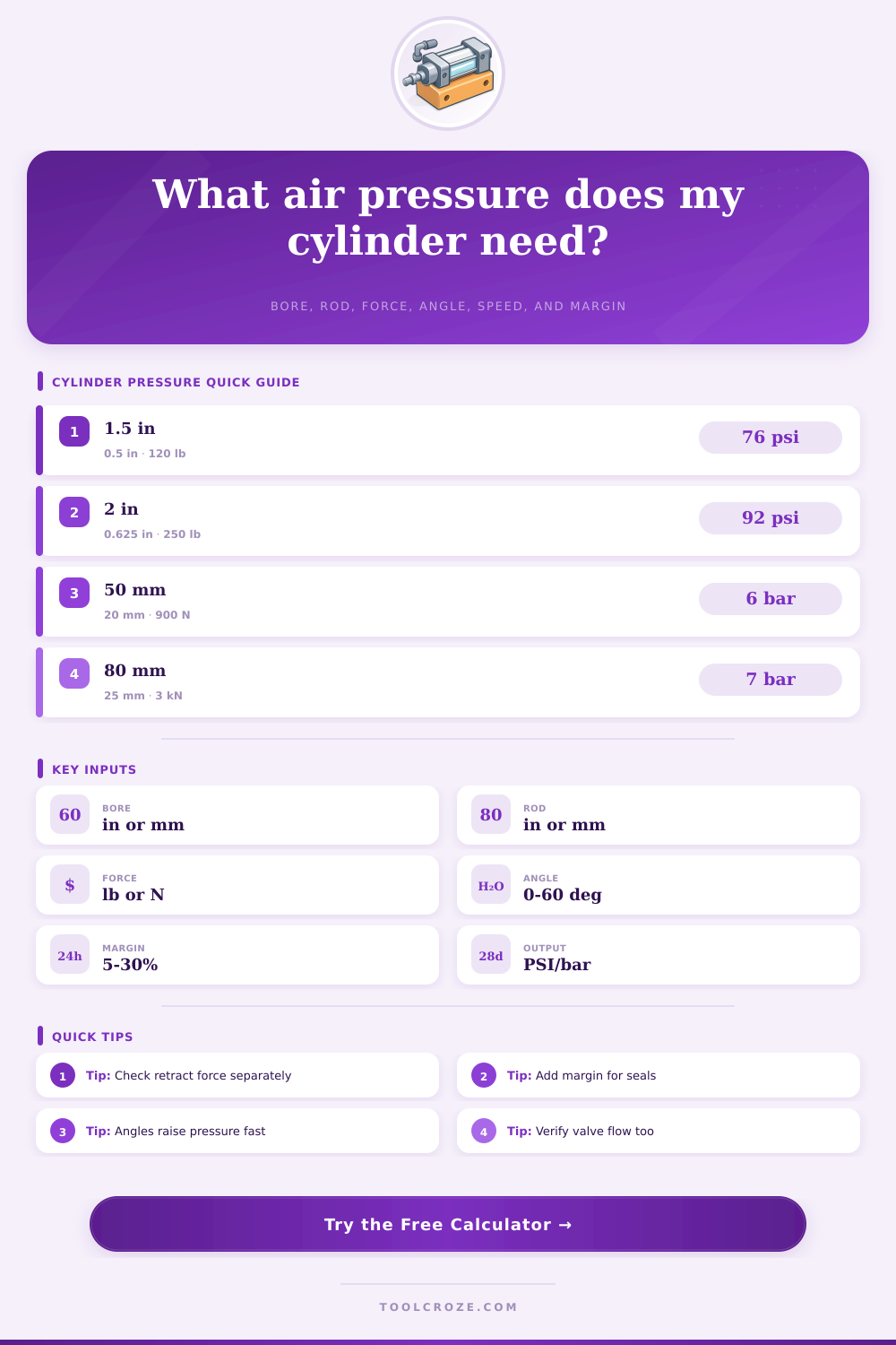
Choose a common actuator case, then adjust the numbers for your cylinder, linkage, regulator, and valve flow.
| Bore size | Extend area | Retract note | Use case |
|---|---|---|---|
| 1 in / 25 mm | 0.79 in² | Rod loss is noticeable | Light clamps, gates, stops |
| 1.5 in / 40 mm | 1.77 in² | Good small automation size | Pushers and light tooling |
| 2 in / 50 mm | 3.14 in² | Common general cylinder | Fixtures and slide tables |
| 3.25 in / 80 mm | 8.30 in² | High force, higher flow | Lift assists and press work |
| 4 in / 100 mm | 12.57 in² | Check valve and port size | Heavy doors and forming |
| System pressure band | Typical range | Design note | Calculator meaning |
|---|---|---|---|
| Low pressure air | 40 to 60 psi | Soft contact or light loads | Good when force margin is wide |
| Plant air nominal | 80 to 100 psi | Most industrial pneumatic sizing | Compare regulator result here |
| High air setting | 110 to 125 psi | Verify components are rated | Use only when required |
| Metric plant air | 5.5 to 7 bar | Common ISO equipment range | Same model shown as bar |
| Friction source | Typical allowance | Where it appears | Sizing advice |
|---|---|---|---|
| Clean cylinder only | 5% to 10% | Seal drag and grease | Use for free-moving rods |
| Guided slide | 10% to 25% | Bearings, seals, carriage | Use measured slide drag if known |
| Dirty fixture | 20% to 35% | Chips, dust, worn guides | Add margin or clean guides |
| Side-loaded rod | 25%+ | Binding and bearing stress | Use a guided actuator instead |
| Stroke speed target | Air demand effect | Motion behavior | Hardware to check |
|---|---|---|---|
| 1 to 3 in/sec | Low flow | Slow clamp or controlled lift | Small valve, meter-out controls |
| 4 to 10 in/sec | Moderate flow | General machine motion | Valve Cv, tubing length |
| 12 to 24 in/sec | High flow | Fast push or eject | Ports, exhaust, cushion setting |
| Over 24 in/sec | Very high flow | Impact risk increases | Shock absorber and load energy |
Pneumatic cylinders use a compressed air to produce linear forces. The pressure requirement of the pneumatic cylinder depend on many factors. The size of the piston is just one of the factor to consider, but it isnt the only one.
The rod on the cylinder take up space on the retract side of the cylinder. Additionally, the angle of the linkage of the pneumatic cylinder and the friction in the cylinder also plays a role in the pressure requirement of an pneumatic cylinder. A pneumatic cylinder pressure calculator that accounts for the area of the piston in both direction, the friction in the cylinder, and the angle of the linkage can save a person the trouble of using trial and error methods to find the correct regulator setting for the pneumatic machine.
Find the Right Air Pressure for a Pneumatic Cylinder
The inputs for the pneumatic cylinder pressure calculator are the diameter of the bore of the pneumatic cylinder, the diameter of the rod of the pneumatic cylinder, and the amount of force the load require from the pneumatic cylinder. From these inputs, the pneumatic cylinder pressure calculator can determine the area of the piston in the extend and retract stroke of the pneumatic cylinder. Since the rod take up space when the pneumatic cylinder retracts, the area is smaller for the retract stroke of the pneumatic cylinder.
The calculator will show which stroke (extend or retract) is the limiting stroke. The pneumatic cylinder will stall if the system is sized to allow for the required force for the extend stroke of the pneumatic cylinder but not for the retract stroke. The angle of the linkage and the friction between the moving part of the pneumatic cylinder can also affect the pressure requirement.
If the pneumatic cylinder is not in the same plane as the load being moved by the pneumatic cylinder, only part of the force of the pneumatic cylinder will move the load. The remaining portion of the force may instead result in the rod of the pneumatic cylinder bending or getting stuck in there guide. Friction between the moving parts of the pneumatic cylinder can also reduce the amount of force available to move the load.
These factor are included in the adjusted load value of the pneumatic cylinder pressure calculator so that the calculated value for pressure reflects the actual force requirements of the pneumatic cylinder rather than the ideal value for an pneumatic cylinder that is aligned with the load and has no friction in its moving parts. Now that a person knows the pressure requirement for a pneumatic cylinder, they must also decide on the regulator setting for the pneumatic cylinder. Since pneumatic cylinders usually require more pressure to produce the necessary force, people may need to add a margin of safety above the calculated value for the pressure requirement of the pneumatic cylinder.
This margin setting is included in the pneumatic cylinder pressure calculator. Additionally, the pneumatic cylinder pressure calculator will ask for the supply pressure of air to the pneumatic cylinder. Based on the recommended regulator value for the pneumatic cylinder, the pneumatic cylinder pressure calculator will indicate whether there is enough headroom in the supply air pressure to supply the pneumatic cylinder or whether the air pressure in the plant is too low for the pneumatic cylinder.
The value for the supply pressure to the pneumatic cylinder is not the only value of interest regarding the pneumatic cylinder. A pneumatic cylinder also requires a certain amount of air flows. A pneumatic cylinder having the correct force for a given load may require a larger bore size to allow for the necessary flow rate of air to the pneumatic cylinder.
This free-air equivalent value must also be considered with the force requirements of the pneumatic cylinder. The size of the air valve, the diameter of the tubing, and the compressor have an impact on the air flow to the pneumatic cylinder. A pneumatic cylinder that has the correct force but does not have enough air flow will exhibit poorly performance.
The materials from which people make pneumatic cylinders have an impact on the force calculations of the pneumatic cylinder. Aluminum tubes are very common for pneumatic cylinders. However, aluminum metal flexes more than steel metal under lateral side loads.
Stainless steel pneumatic cylinders are more corrosion resistant than steel pneumatic cylinders. However, the seals used for stainless steel pneumatic cylinders may have more friction than those used for pneumatic cylinders having steel bodies. Rodless pneumatic cylinders do not have a rod extending from the pneumatic cylinder.
Therefore, there is no area difference between the pneumatic cylinder’s extend and retract strokes. Additionally, there are no rod seal to consider for rodless pneumatic cylinders. The information regarding force calculations for pneumatic cylinders does not account for these variable.
However, unless a person is manufacturing pneumatic cylinders for specific application, they should of a basic understanding of the different type of pneumatic cylinders to make sure the friction and angle variable entered into the pneumatic cylinder pressure calculator are realistic. One of the common mistake people make when sizing pneumatic cylinders is using the bore size of the pneumatic cylinder as the only important specification for pneumatic cylinders. A pneumatic cylinder with a 2-inch bore and a 0.5-inch rod require more force to move the same load than a pneumatic cylinder with a 2-inch bore and a 0.75-inch rod.
Another of the common mistake people make is forgetting that the pressure value of the pneumatic cylinder is less than the pressure value of the air compressor. The pressure of the pneumatic cylinder will be less than the air compressor due to pressure drops across the filters, tubing, and quick-exhaust valve. This supply pressure of the pneumatic cylinder is the value that the pneumatic cylinder pressure calculator should ask for when setting up the pneumatic system.
The tables listed on this page have information regarding the bore sizes of pneumatic cylinders, the pressure bands that pneumatic components operate at, and the friction values for different pneumatic application. These tables are not the means to determine the friction value of a pneumatic system’s moving parts. However, they can provide a starting point to fine-tune the pneumatic system to match the requirements of the pneumatic machine.
The tables also include the range of speed at which pneumatic cylinders should operate. Knowing the speed of the pneumatic cylinder will allow people to determine the size of the air valve needed to control the pneumatic cylinder. When a person gets the result from the pneumatic cylinder pressure calculator, they should look at the recommended regulator pressure and the supply check to determine whether the plant air pressure can perform the required tasks of the pneumatic cylinder.
The air pressure at the pneumatic cylinder will be less than the air pressure at the plant’s air compressor. If there is a large difference in pressure between the supply air to the pneumatic cylinder and the air at the pneumatic cylinder, small change in friction or angle will have a major impact on the performance of the pneumatic cylinder. In such situations, the person in charge of the pneumatic system could adjust the supply pressure, change the angle of the linkage, or change the bore size of the pneumatic cylinder.
These recommendation are all visible from the results of the pneumatic cylinder pressure calculator. Using these numbers in the pneumatic cylinder design allows people to make informed decision about how to best operate the pneumatic cylinder. A pneumatic cylinder that requires 85 psi to perform its task is less likely to cause wear and tear on the system’s component than a pneumatic cylinder that requires 115 psi to perform its task.
Using the correct pressure will reduce the amount of heat and noise created by the pneumatic cylinder. Additionally, using the correct pressure will also make the pneumatic cylinder last longer by reducing the number of time people have to change the pneumatic cylinder’s component. Using the pneumatic cylinder pressure calculator will allow people to find the right value for the supply pressure of the pneumatic cylinder.
This supply pressure will allow the pneumatic cylinder to handle condition that are not specified on the original drawing of the pneumatic machine.