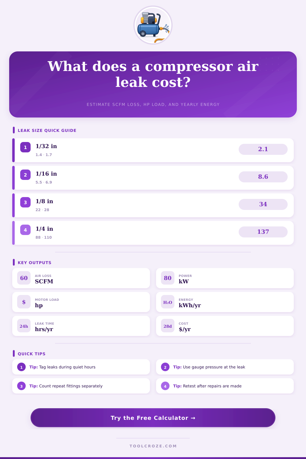
Compressor Air Leak Calculator
Estimate compressed air leak loss from orifice diameter, count, pressure, operating hours, compressor efficiency, and electricity rate.
▣Leak Presets
Use a measured hole size, ultrasonic estimate, drill gauge, or fitting class. Each preset fills a realistic plant air leak scenario.
⚙Leak Inputs
This sets the discharge coefficient used in the orifice flow estimate.
Count repeated leaks of the same estimated size.
Use the round-hole diameter that best matches the leak opening.
Use gauge pressure near the leaking point, not receiver cut-out pressure.
Include nights and weekends if the header remains pressurized.
Use operating calendar days for the compressed air system.
Typical lubricated rotary screw systems are often near 17 to 22 kW per 100 SCFM.
Use your blended energy rate when available.
Leak Loss Results
▦Leak / Material / Spec Comparison
ℹLeak Reference Tables
| Equivalent Hole | Typical Source | Approx. SCFM at 100 psig | Equivalent HP at 18.5 kW/100 SCFM |
|---|---|---|---|
| 1/64 in | Small thread seep or stem leak | 0.4 SCFM | 0.10 hp |
| 1/32 in | Audible coupler hiss | 1.7 SCFM | 0.42 hp |
| 1/16 in | Tube nick or worn quick connect | 6.9 SCFM | 1.71 hp |
| 1/8 in | Open drain, broken fitting, cut hose | 27.7 SCFM | 6.87 hp |
| 1/4 in | Open line or failed valve seat | 110.8 SCFM | 27.5 hp |
| Leak Path | Coefficient Used | Best Use | Uncertainty Note |
|---|---|---|---|
| Sharp-edged hole | 0.62 | Drilled plate, puncture, clean wall opening | Good for round holes |
| Threaded fitting gap | 0.58 | Couplers, unions, valve packing | Often irregular |
| Short open tube | 0.72 | Cut hose, open nylon tube, nozzle | Higher flow path |
| Gasket split | 0.50 | Flange seam, diaphragm edge, valve cover | Map slot to round area |
| Porous vent | 0.35 | Mufflers, sintered exhausts, dirty vents | Lower free area |
| Gauge Pressure | Flow Multiplier vs 100 psig | Common Use Case | Leak Behavior |
|---|---|---|---|
| 60 psig | 0.58 | Low-pressure tools and blowoff | Usually choked above 13.7 psig |
| 80 psig | 0.79 | General shop air header | Flow tracks absolute pressure |
| 100 psig | 1.00 | Typical plant air setpoint | Reference condition |
| 125 psig | 1.26 | Higher-pressure receiver systems | Leak loss rises quickly |
| 150 psig | 1.52 | Specialty air storage or process air | Repair priority increases |
| Compressor Type | Typical Efficiency Input | Useful Range | When to Adjust |
|---|---|---|---|
| Lubricated rotary screw | 18 to 21 kW/100 SCFM | Steady plant load | Use actual package kW if metered |
| Two-stage reciprocating | 16 to 19 kW/100 SCFM | Intermittent shop load | Use loaded kW, not nameplate hp |
| Oil-free screw | 20 to 25 kW/100 SCFM | Process or clean air | Include dryer pressure drop if measured |
| Centrifugal compressor | 17 to 22 kW/100 SCFM | Large baseload systems | Check blowoff and turndown losses |
✓Leak Calculation Tips
Compressed air systems provide power to factories. However, the leaks in those systems can create high costs for the factorys that purchase and use those systems. The leaks in a factorys compressed air system may be small hisses at the fitting or small crack in the hose.
Each of these leaks can cost the factory thousands of dollar each year. Many of these plants do not know the exact amount of air that is being lost to these leaks since they do not measure the air loss in the plants. However, the calculator tool will allow a factory to calculate the cost of the air leaks in the system by entering the size of the leak, the pressure of the system, and how often the system are in use.
How to Calculate the Cost of Air Leaks
The calculation of the size of the leak depend upon the principle of orifice flow. The orifice flow depends upon the size and shape of the opening where the air leave the system and the pressure of the air that exits the system. For example, the amount of air that can exit through a sharp edged hole may not be the same than the amount of air that would exit through a short length of tubing that has been cut to allow for the release of the air.
The use of a coefficient of discharge allows for these difference in air outflow to be accounted for in the estimate of the number of standard cubic feet of air that is lost per minute through each leak. By multiplying this number by the number of identical leaks within the system, you can determine the total volume of air that is lost to leaks in the system each minute. The air pressure within the system is another factor that will impact the size of the leak.
The higher the pressure of the air within the system, the more air will leak out of the system. The reason for this is due to the relationship between the pressure of the air within the system and the density of the air that is leaking out of the system. If the pressure of the air is higher, the density of that air will be higher, meaning that more air will be able to pass through each leak.
For example, a leak in the system that is considered to be tolerable at 80 psig may release too much air if the pressure of that system is increased to 125 psig. The calculator uses the pressure that is entered into the calculator to determine whether the leak in the system is choked or subcritical. Based on this determination, the calculator is able to make an accurate estimation of the size of the leak.
The volume of air that is lost in the system can be converted to a unit of power. The air compressor for the facility must supply the volume of air that is lost in the system. The production of compressed air requires the use of electricity.
Therefore, the user can enter the efficiency of the compressor in the facility into the calculator in the units of kilowatts per 100 SCFM. By entering this value into the calculator, the system can determine the number of horsepower units that are lost by the system and the number of kilowatt-hours of electricity that is cost to the facility each year. The number of hours that the system is in operation is another factor that will impact the facility’s cost of air leaks.
The facility uses the number of hours that the system is in operation to determine the cost of air leaks during the hours that the facility is in operation. For example, if the air system in a facility only operates during the day shift, the system may be under pressure to provide air during the night shift or on the weekends. As such, the calculator accounts for the total number of operating hours within the calendar year.
The cost of air leaks during these off-shift hours is likely to be higher than the cost during the facilitys production time. The tables included with this project can help to provide context for the various size of air leaks in a system. The tables show the airflow rates for holes of different sizes, from pinhole sizes to quarter inch gaps in air hoses.
The tables also provide the values for the discharge coefficient for these different sizes of air leaks. These coefficients are based upon empirical tests of the size of air leaks that have been performed in various systems. Using these coefficients will allow the calculation of the size of air leaks to be accurate.
Based upon the calculation of the cost of air leaks in the facility, it is possible to decide which air leaks to repair first. Large leaks in air lines can be easily detected visually. However, small leaks at the fittings in the air lines may be more numerous but contribute to a higher total loss of air.
Using the calculator, it is possible to group together small leaks to determine the total cost of air loss from only those leak. This information can help to prioritize repairs to the system. Additionally, the calculator can determine if reducing the pressure that is applied to the system would also reduce the volume of air that leaks from the system.
This information can help to determine if reducing the pressure within the system is an ideal decision for the facility. Due to the factors described above, it is possible to understand how the air leaks in a facility may not behave according to the specifications in the calculator. For instance, the temperature of the air within the system can change over time, affecting the density of the air that is leaking from the system.
Additionally, the vibration that may occur within the system over time can lead the leaks in the system to expand over time. Additionally, the corrosion of the inner pipes of the system may create leaks that are not as defined as those accounted for in the calculator. However, the calculator for determining the cost of air leaks within the system can provide a baseline to compare the cost of different air leaks.
Based upon the calculations of the cost of each leak in the system, it is possible to decide whether the use of more accurate leak detection technology, such as ultrasonic leak detectors or soap and water leak detectors, may be beneficial for that facility. The detection of air leaks can lead air compressor manufacturers to repair the leaks in the system. The user may compare the cost of repairing these leaks with the cost of energy that is lost due to the leaks to determine if the repair is a good decision.
For example, if the cost of air energy loss within a year is higher than the cost of repairing the leaks, then the repair to those leaks is usually a good decision. Additionally, the calculator allows for adjustments to be made to the cost of repairs to the system to determine if the air leak repairs are a good idea for the facility. Air leaks within a factory can consist of many small leaks.
The cost of each of these leaks may not become visible without the use of the calculations of the costs of these leaks. By running the numbers for the cost of air leaks within your own facility, it is possible to gain an understanding of the total cost of the air leaks in your facility. Additionally, by gaining an understanding of the cost of air leaks, the facility can recognize the leaks as losses of the facilitys earnings.