Air Compressor CFM Calculator
Run a receiver tank fill test, convert pressure rise into free air, apply duty-cycle and correction factors, then compare the result to common compressor specs.
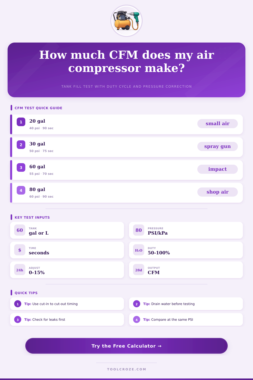
⚙CFM Test Presets
Choose a real shop scenario or enter your own tank fill data from cut-in pressure to cut-out pressure.
📏Tank Fill Test Inputs
Use the actual tank or receiver volume stamped on the vessel.
Record the pressure where the pump starts.
Record the pressure where the pump stops.
Time only the pressure rise between the two gauge readings.
Use the compressor rating or the duty cycle you want to respect.
Add for leakage, warm air, altitude, hose loss, or conservative sizing.
Used for target-pressure free-air conversion and refill estimate.
Standard air conversion uses absolute temperature.
Measured Tank-Test CFM
0.0
Corrected Free-Air CFM
0.0
after correction factorContinuous Usable CFM
0.0
after duty-cycle limitTarget Pressure Free Air
0.0
SCF stored in receiver at targetEstimated Target Fill Time
0.0
minutes from empty receiver to targetPressure Rise Rate
0
psi per minute during test📊Compressor Spec Comparison Grid
2-4
CFM trim compressor range at 90 psi
5-8
CFM common garage compressor range
10-15
CFM small shop belt-drive range
18+
CFM high-demand continuous air range
📘Reference Tables
| Receiver Size | Typical Test Rise | Good Timing Window | Reading Notes |
|---|---|---|---|
| 6 to 10 gal portable | 30 to 50 psi | 40 to 120 seconds | Use a short test and repeat twice because small tanks magnify gauge error. |
| 20 to 30 gal garage | 40 to 55 psi | 60 to 150 seconds | Time from cut-in to cut-out with the drain closed and no tools running. |
| 60 gal shop receiver | 40 to 60 psi | 60 to 180 seconds | Allow the pump to cool between tests if duty cycle is below 100%. |
| 80 to 120 gal receiver | 50 to 70 psi | 90 to 240 seconds | Large tanks reduce stopwatch error and show more stable CFM. |
| Air Tool Load | Typical Working Pressure | Approx. Demand | Duty-Cycle Advice |
|---|---|---|---|
| Brad nailer or stapler | 70 to 100 psi | 0.5 to 2 CFM intermittent | Tank reserve matters more than continuous CFM for short bursts. |
| Impact wrench or ratchet | 90 psi | 4 to 8 CFM intermittent | Use corrected CFM and allow recovery time between heavy pulls. |
| HVLP spray gun | 25 to 45 psi at gun | 9 to 14 CFM steady | Continuous usable CFM should meet or exceed the gun rating. |
| Small abrasive blaster | 80 to 100 psi | 12 to 25 CFM steady | Use high duty cycle and add a correction margin for pressure drop. |
| Correction Item | Suggested Factor | When to Apply | Calculator Input |
|---|---|---|---|
| Small fitting or hose drop | +3% to +5% | Long hose, quick couplers, or narrow regulator paths. | Enter 3 to 5 in correction factor. |
| Minor leak allowance | +5% to +10% | Receiver holds pressure but shop piping has slow leakage. | Enter 5 to 10 after repairing obvious leaks. |
| Conservative sizing | +10% to +15% | Selecting compressor capacity for steady production use. | Enter 10 to 15 for planning margin. |
| Known clean lab test | 0% | Short pipe, accurate gauge, cool pump, and repeated readings. | Enter 0 to report measured test CFM. |
| Pressure Term | Meaning | Formula Use | Common Mistake |
|---|---|---|---|
| Gauge pressure | Pressure shown on the tank gauge above atmosphere. | Use pressure rise in psi for a fill test. | Adding atmospheric pressure to both readings before subtracting. |
| Absolute pressure | Gauge pressure plus atmospheric pressure. | Useful when converting full stored air at one pressure. | Calling psig and psia the same value. |
| Free air | Equivalent air volume expanded back to atmospheric pressure. | CFM output is reported as free air delivery. | Using tank cubic feet as delivered air without pressure conversion. |
| SCFM | Free air adjusted to a standard temperature reference. | This calculator applies a 520 R temperature factor. | Comparing hot-field CFM to a standard rating without correction. |
💡Test Tips And Safety
A tank fill test is used to measure the amount of air that a compressor will actualy output. Many compressors dont provide the amount of air that is shown on the compressor’s label. To determine the actual output of the air compressor, a tank fill test is require.
The output of an air compressor can be influenced by a variety of factors, including the performance of the pump itself, the size of the air tank, and the duty cycle of the motor that runs the compressor. The calculator that follows this article can account for each of these factor. Performing a tank fill test is actually a very simple process, all that is required is to time the compressor as it fills the tank with air.
How to Do a Tank Fill Test
The time that the compressor take to fill the tank to a specific pressure can be used to calculate the volume of free air that the compressor pumped out of its intake during that cycle. The air within the tank is compressed, so the cubic feet that is indicated on the pressure gauge are not the same as the cubic feet of outside air that is drawn into the compressor. The user can calculate the volume of free air using the starting pressure of the tank, the ending pressure of the tank, the size of the tank, and the temperature of the air.
Furthermore, the user can adjust the calculated volume of free air according to in what way that air will be utilized. Many people choose to perform the tank fill test between the cut-in and cut-out pressures of the compressor. These pressures are the exact same pressures that the compressor use to control the motor that runs the compressor.
Using these pressures will result in the largest measurement of the amount of air that the compressor can output. Yet, a larger range of pressures means that it will take longer for the compressor to reach the end of the test. For instance, it will take a longer period of time for a sixty-gallon tank to rise to forty psi than it will take for a twenty gallon tank to reach that same pressure.
Furthermore, because it will take less time to perform the tank fill test with the small tank, there is a chance of introducing error into the measurement of the output of the compressor. Thus, the use of a pressure band between the cut-in and cut-out pressures of the air compressor is preferred. The gas law calculations that are performed in this calculator will allow for users to compare the output of the compressor to the specifications provided by the air compressor manufacturer.
The duty cycle of the motor is another important variable to consider in determining the output of the air compressor. For instance, if the air compressor outputs twelve cubic feet of air per minute, but the motor has a duty cycle of only seventy percent, then the amount of air that can be continuously dispensed from the air compressor is only eight and a half cubic feet of air per minute. Tools that require a continuous supply of air to function properly (like an HVLP spray gun) will require that the duty cycle of the motor is sufficient to supply the air to that tool.
Correction factors can be utilized to account for the difference between the ideal air compressor system and the actual air compressor system that is in use in the workshop. Factors like leaks in the system, the length of the air hoses, the altitude in the area, and the temperature of the air within the compressor can each have a negative impact upon the amount of air that reaches the tool. A percentage can be entered in the correction field to indicate how much more air the air compressor must produce to overcome these losses.
The stored-air calculation can be utilized to determine how long the air tank will provide air to the tool. If the user determines the amount of cubic feet of free air that are stored within the tank at a specific pressure, the length of time that that air will provide air to the tool can be calculated. This can help to determine if the air tank is large enough to avoid the motor that runs the compressor from cycling on and off too often.
There are some common mistakes that many people make when they are performing this tank fill test. For example, it is common for individuals to forget to drain the water from the air tank prior to the test. If there is water within the tank, the pressure of the tank can be inaccurately.
Furthermore, it is also common to start the tank fill test while the air compressor is still cold. The motor should be allowed to reach normal operating temperature prior to the test. Finally, many people will compare the results of their tank fill test directly to the specifications printed on the air compressor.
These comparisons do not account for the difference in air pressure and temperature. Instead, users should use the reference tables that is included in the calculator to compare the results of their test. It is common for air systems to lose some of the air pressure between the air compressor and the air tool.
For instance, an HVLP spray gun might require an air pressure of eleven or twelve cubic feet per minute to function proper, even if the air tool is only rated for nine cubic feet per minute. Accounting for these losses of air pressure will ensure that the air compressor is large enough to supply the air to the air tools that are used within the shop. The temperature of the air can have a negative impact upon the amount of air that is moved by the air compressor.
Hot air is less dense than air at room temperatures, so the air compressor will move fewer pound of air if the air within the air compressor is hot than if the air is cold. The temperature that is entered into the calculator should be the actual temperature of the air in the shop where the air compressor will be used. The temperature field uses the absolute Rankine scale to calculate the effects of air temperature upon the total amount of air that is moved by the air compressor.
Another factor that can impact an air compressor is the altitude at which the air compressor is used. At high altitudes, the air compressor will have to work harder to achieve a given air pressure within the tank. Furthermore, the amount of free air that the air compressor delivers decreases at high altitudes.
The correction field can be used to account for these effects of altitude. Alternatively, the user can simply test the air compressor at its current altitude. If a person is considering purchasing two air compressors of similar specifications, the duty cycle and the continuous usable air figures can be used to determine which air compressor will best meet the air demands of the tools that are to be used.
Tools that are used intermittently (like nail guns) do not require as much air from the air compressor as tools that are continuously used. Tools that are continuously used require the duty cycle of the air compressor to have a sufficient amount of air provided to the tool by the motor of the air compressor. To ensure the accuracy of the results of the tank fill test, a few steps should be taken prior to beginning the test.
First, the drain on the air tank should be closed. Second, all air tools that is connected to the air compressor should be turned off. Third, the air compressor should be allowed to cycle its motor on and off during the test.
Finally, the test should be performed two separate times, and the result from each time should be averaged if the two measurements of the amount of air that is output from the air compressor are different from one another. Following these steps will ensure that the measurement of air that the compressor can output is a number that can be trusted by the user.