Fire Hose Friction Loss Calculator
Estimate fire hose friction loss, pump discharge pressure, flow per line, elevation pressure, appliance loss, and parallel-line savings using the coefficient method.
Load a named fireground stretch, then adjust GPM, hose diameter, length, coefficient, appliance loss, elevation, nozzle pressure, and parallel lines.
Calculation Breakdown
| Hose size | Planning C | Common flow band | Typical use |
|---|---|---|---|
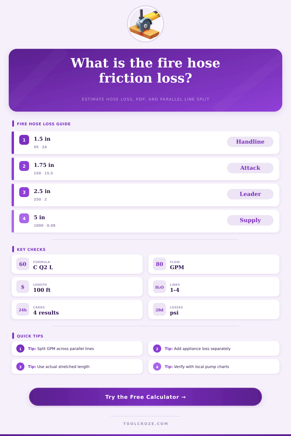
| 1-1/2 in attack hose | 24 | 60 to 125 GPM | Older handline, standpipe pack, short stretch |
| 1-3/4 in attack hose | 15.5 | 125 to 185 GPM | Primary attack handline with fog or smooth bore nozzle |
| 2 in attack hose | 8 | 160 to 250 GPM | High-flow handline with lower friction than 1-3/4 in |
| 2-1/2 in hose | 2 | 200 to 325 GPM | Leader line, heavy handline, portable monitor supply |
| 3 in hose | 0.8 | 300 to 600 GPM | Supply line, relay line, blitz attack line |
| 4 in supply hose | 0.2 | 500 to 900 GPM | Large supply line with moderate flow |
| 5 in LDH | 0.08 | 800 to 1500 GPM | Hydrant supply, aerial device, master stream supply |
| Item | Planning loss | Where to enter it | Field note |
|---|---|---|---|
| Gated wye or manifold | 10 to 15 psi | Appliance loss | Use department chart for high-flow devices |
| Master stream appliance | 15 to 25 psi | Appliance loss | Monitor, deck gun, or portable ground monitor |
| Foam eductor | 30 to 35 psi | Appliance loss | Confirm required inlet and nozzle pressure |
| Standpipe elevation | 5 psi per floor | Elevation change | Equivalent to about 10 ft per floor |
| Aerial waterway | See device chart | Appliance loss | Many aerial devices have separate waterway loss tables |
| Uphill or downhill stretch | 0.434 psi per ft | Elevation change | Positive uphill increases PDP, downhill subtracts |
| Layout | Total GPM | Flow per line | Why it changes loss |
|---|---|---|---|
| Single 2-1/2 in line | 500 GPM | 500 GPM | All water uses one friction path |
| Dual 2-1/2 in lines | 500 GPM | 250 GPM | Quarter of the hose loss per path at same length |
| Dual 3 in supply lines | 800 GPM | 400 GPM | Lower pressure drop can support relay or master stream flow |
| LDH single supply | 1000 GPM | 1000 GPM | Large bore keeps velocity and coefficient low |
When a fire department crew is using a hose to fight a fire, the pump operator have to calculate the friction loss between the discharge valve and the nozzle. Friction loss is the reduction of the water pressure that occur as the water rubs against the inside of the hose. The friction loss between the pump and the nozzle is important to calculate because the difference between the two value will indicate the pump pressure and the nozzle pressure.
If the pump operator does not account for friction loss, the nozzle pressure may be too low to assist in extinguish the fire. Thus, by calculating friction loss, the fire department can determine the required pump pressure to deliver the necessary nozzle pressure. Friction loss occur as the water rubs against the inside of the hose.
Friction Loss in Fire Hoses and Pump Pressure
Factors that contribute to friction loss include the roughness of the interior of the hose, the flow rate of the water through the hose, the diameter of the hose, and the length of the hose. Each of these factors is important in determining the total friction loss in the hose, as each of these variables contribute to the rubbing of the water against the interior of the hose. Factors that contribute to friction loss include the diameter of the hose, the length of the hose, and the flow rate of the water.
Each of these variables is crucial to calculating the total friction loss in a water hose. Elevation also creates changes in the pressure that the fire department’s pump must provide. Because water has weight, if the nozzle is elevated in relation to the pump, the pump must provide additional pressure to push the water to that elevation.
For example, water weighs 8 lbs per gallon of water. Thus, if the nozzle is elevated one foot above the pump, the pump must provide an additional half-pound of pressure to the water to push it to that nozzle. In high-rise structures, the elevation is also a critical factor to the fire department crew in calculating the required discharge pressure from the pump.
The fire department crew must measure the elevation of the fire department’s nozzle relative to the pump to determine the height of the floors that must be overcome by the water. In addition to the elevation of the nozzle, appliances that are placed in between the pump and the nozzle will reduce the pressure of the water that is discharged from the nozzle. Appliances can include items like a gated wye, a monitor, and an aerial waterway.
Each of these appliances will require a specific amount of inlet pressure to ensure proper function of that appliance. Thus, in addition to friction loss in the hoses, the fire department must also calculate the inlet pressure to each of these appliances to determine the total system pressure that is required from the fire department’s pump. If the pump operator does not account for the inlet pressure of the appliances, the pump will be underestimated in its required pressure to overcome the friction loss and provide sufficient nozzel pressure.
Using parallel lines of hose between the pump and the nozzle can significantly reduce the total friction loss in the system. By using two or more hoses of the same diameter to carry the same total amount of water, each individual hose will contain less of the total flow of water. Thus, friction loss in each individual hose will be significantly reduced.
This reduction in friction loss allow the pump to deliver the same amount of water to the nozzle without working as hard to overcome the friction loss in the hoses. A coefficient is a number that indicates the friction loss of a specific type of hose. Testing of those specific hoses calculates this coefficient.
The coefficient may change if the hoses age or if the interior of the hoses become damaged. Thus, a coefficient is a published number that can be used to calculate the friction loss of the hoses, but the actual pressure measurements at the pump may differ slightly from the calculations. Thus, the difference between these two values can indicate the performance of the hoses relative to the calculations.
There are a few mistakes that many fire department members can make in performing friction loss calculations. One mistake includes using the laid length of the hose rather than the stretched length. If such calculations are made with the laid length of the hose instead of the stretched length, the friction loss will be underestimated.
Another mistake is to forget to split the flow of water if using parallel lines. Thus, if the flow is not divided between the two hoses, the total friction loss will be overestimated. A third common mistake is to leave out the inlet pressure of the appliances in calculating the total friction loss.
Thus, if the inlet pressure of the appliances is left out of the calculation, the calculated total system pressure will appear to be higher than the true system inlet pressure that is provided by the engine. In order to avoid mistakes in calculating friction loss, the fire department can perform the calculations prior to charging the hose with water. The pump operator can verify the calculations after beginning to charge the hose with water.
For instance, the nozzle crew will begin to hear the water exiting the nozzle, the pressure at the pump will begin to rise, and the nozzle crew will begin to feel the water pressure at the nozzle. By performing calculations prior to charging the hose and by comparing those calculations to the actual system performance after the system is charged with water, the fire department can learn how well their hoses and appliances perform relative to expected performance. Furthermore, by calculating the difference between the total system pressure from the pump and the nozzle pressure, the fire department can determine whether any adjustments are needed for the water flow rate or the number of hoses that must be used to fight the fires.