Fire Hose Pressure Calculator
Estimate pump discharge pressure from flow GPM, hose diameter, length, elevation, nozzle pressure, appliance loss, and the fire-hose friction coefficient used by your department.
Pick a common attack, backup, standpipe, master stream, or supply layout. Each preset fills the GPM, hose diameter, length, elevation, nozzle pressure, appliance loss, and coefficient.
Calculation Breakdown
| Hose diameter | Typical coefficient | Common flow range | Planning use |
|---|---|---|---|
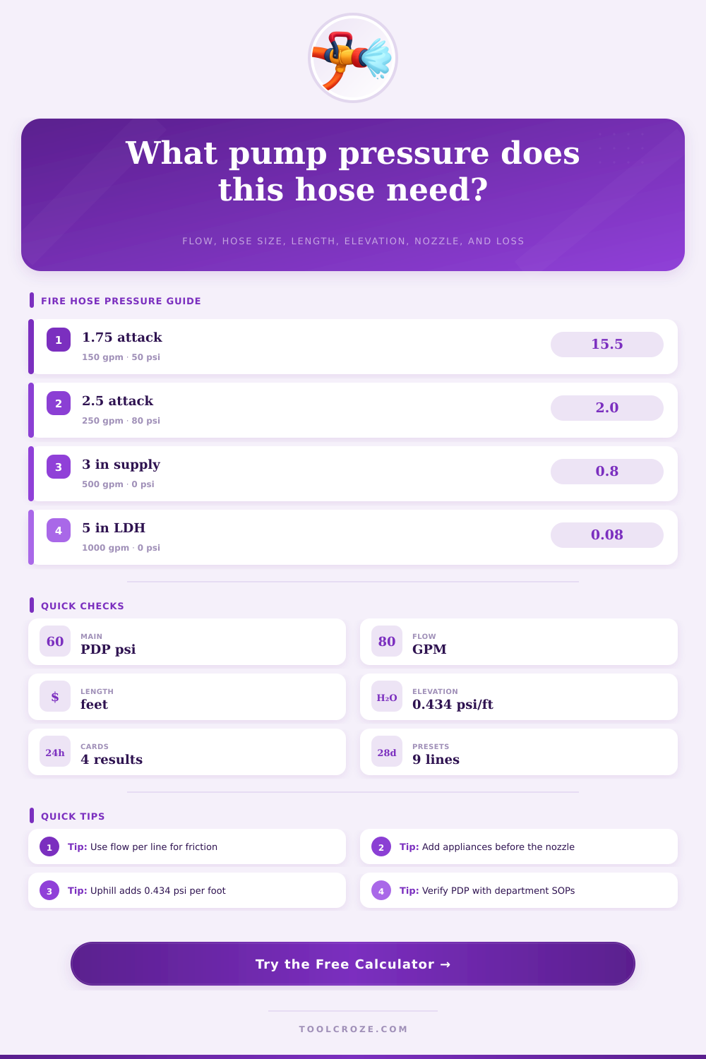
| 1-1/2 in attack hose | 24 | 95 to 125 GPM | Older attack packs, forestry, or compact stretches. |
| 1-3/4 in attack hose | 15.5 | 125 to 185 GPM | Common residential attack line and crosslay. |
| 2 in attack hose | 8 | 160 to 250 GPM | High-flow attack line with lower friction than 1-3/4 in. |
| 2-1/2 in handline | 2 | 200 to 325 GPM | Commercial attack, exposure line, or master stream feed. |
| 3 in supply hose | 0.8 | 300 to 600 GPM | Supply, relay, standpipe feed, or portable monitor feed. |
| 5 in LDH | 0.08 | 750 to 1500 GPM | Relay and hydrant supply where appliance loss may dominate. |
| Device or nozzle | Typical pressure | Where entered | Fireground note |
|---|---|---|---|
| Combination fog nozzle | 100 psi | Nozzle pressure | Confirm if your nozzle is automatic, fixed, or low pressure. |
| Low-pressure fog nozzle | 75 psi | Nozzle pressure | Often used to reduce reaction while keeping a fog pattern. |
| Smooth bore handline | 50 psi | Nozzle pressure | Use the actual tip flow for the GPM input. |
| Master stream smooth bore | 80 psi | Nozzle pressure | Deck guns and monitors may add appliance loss before the tip. |
| Wye, gated valve, or standpipe outlet | 10 to 25 psi | Appliance loss | Add the known device loss from SOPs or manufacturer data. |
| Foam educator or portable monitor | 25 psi or more | Appliance loss | Check device requirements before committing the line. |
| Scenario | Elevation input | Pressure effect | Planning note |
|---|---|---|---|
| Flat residential stretch | 0 ft | 0 psi | Use hose length, nozzle pressure, and appliance loss only. |
| Second-floor attack | 12 to 18 ft | 5 to 8 psi | Small but worth including on marginal long stretches. |
| Fourth-floor walkup | 35 to 45 ft | 15 to 20 psi | Standpipe outlet pressure and hose pack loss both matter. |
| Downhill exterior line | -20 ft | -9 psi | Do not over-throttle if nozzle reaction or pattern is critical. |
| Parking structure ramp | 25 to 60 ft | 11 to 26 psi | Long hose and elevation can stack quickly. |
| Roof or aerial feed | 75 to 100 ft | 33 to 43 psi | Verify the full appliance path and rated pressure limits. |
In deciding how much pressures to send through the hose line, the pump operator must consider how that pressure will impact the water reaching the fires. If the pump operator send too little pressure through the hose line, the water that emerges from the nozzle will not reach the fire. If the pump operator sends too much pressure through the hose line, the reaction force from the water may cause the pump operator to lose there balance, and the excessive pressure can cause the hose line to fail at the couplings.
Thus, the pump operator needs to utilize a means of calculating the pressure that should be discharged from the pump so that the discharge pressure is the correct pressure for that specific hose line. In calculating the pump discharge pressure, there are several different variables that must be considered. The first of these variables is the flow rate of the water, which is measured in gallons per minute.
How to Calculate Pump Pressure for Fire Hoses
The second of these variables is the diameter and length of the hose. Each hose diameter has a coefficient associated with it that helps to represent the friction loss in that specific hose. The third of these variables is the elevation change between the pump and the nozzle.
Because water has weight, the elevation change result in a change of the pressure that must be applied to account for that weight; for every foot that the nozzle is above the pump, the pump must apply 0.434 pound per square inch of pressure. The fourth of these variables is the nozzle pressure required to effectively extinguish the fire. The fifth of these variables is the appliance loss; appliances, such as gated wyes, standpipe outlets, valves, and monitors, each create a loss of pressure that is expressed in pounds per square inch that is lost.
Finally, another allowance that can be added to the equation is for potential problems in the hose line that may not be accounted for yet; a kinked hose, for example, will require additional pressure to push the water through the kink. These variables interact with one another in ways that may be difficult for the pump operator to determine without first performing the calculation. For instance, consider pumping 150 gallons per minute through a 1-3/4 inch hose for 200 feet of hose length.
In this situation, the friction loss will be significant. If the hose must travel 40 feet of elevation to reach the window of a building on the fourth floor of a building, the pump will have to supply an additional 17 pounds per square inch of pressure to overcome the weight of the water. If the firefighter use a larger diameter hose, the friction loss will be less; however, the larger hose will be heavier and have a different nozzle reaction.
Each of these different variables a pressure calculator can account for, allowing the pump operator to focus upon the efficiency of the hose layout rather than the calculations that are necessary to determine the appropriate pressure that should be discharged from the pump. In the real world, each fire scene and each hose layout has its own set of problems. For instance, a hose layout that may otherwise appear to be an efficient layout may have to go around a corner or uphill to the fire.
Additionally, a standpipe pack may not be long enough to supply the stairwell of the building. In these instances, more hose will have to be purchased or located for the firefighters to create an efficient layout; however, that additional length of hose will impact the friction loss and the elevation change in ways that must be accounted for in calculating the proper discharge pressure of the pump. Furthermore, a reference table exists that allows the pump operator to find the coefficient that corresponds to a specific diameter of hose; thus, the pump operator does not have to guess at what that coefficient should be.
Appliance loss is one of the factors that is easy for a pump operator to disregard; however, appliance loss is a factor that must be included in calculating the proper pressure that should be discharged from the pump. Each appliance will lose some of the pressure of the water that exits the pump; many appliances can lose ten to twenty-five pounds of pressure. This loss of pressure is a component that must be accounted for in the total determination of the required pressure at the nozzle.
Additionally, many fire departments instruct the pump operators to add the appliance loss before determining the nozzle pressure. This ensures that the nozzle pressure does not come as a surprise to the pump operator when the nozzle is connected to the hose line. The factor of elevation is another variable that is simple to understand but often unforgiving of mistake.
For every foot that the nozzle is elevated relative to the pump, the pump must provide 0.434 pounds per square inch of additional pressure. That same elevation will impact the nozzle pressure, but negative elevation will not impact the nozzle pressure. Thus, if the hose line is allowed to drop downhill after the nozzle, the elevation will contribute a negative value to the calculation.
However, the negative elevation will decrease the amount of pressure that the pump must create; if the pressure is dropped too low, though, the water will not effectively reach the fire. Some of the most common mistakes made by pump operators are to consider the calculated pressure as the target pressure and to base the flow of water through the hose on the nozzle rating. These mistakes can become more problematic if the pump operator is required to run multiple fire lines from the same pump.
Each fire line will create friction loss and each line will contribute to the total volume of water being discharged from the pump. A pressure calculator will help to avoid these mistakes by asking for the flow rate of each line and the total number of fire lines that are being run. In addition to the pressure of the water that the pump must create, another factor in determining the proper discharge of the pump is the velocity of that water.
High rates of flow through a small diameter hose create high velocities of water. High velocities of water create difficulties in managing the nozzle of the hose line; the reaction of the water from the nozzle can impact the firefighters who are operating the nozzle. Additionally, high rates of velocity of the water in the hose can result in water hammer in the hoselines.
An estimate of the velocity can alert the pump operator if the flow and diameter of the hose are creating dangerous rates of water velocity. In these situations, the pump operator may adjust the diameter of the hose or the flow rate. Every calculation of the required discharge pressure of a fire pump is an estimation based off the assumption that each component of the fire hose line is functioning correct and efficiently.
Each component of the system, from the hoses to the couplings, appliances, and pump can age and be damaged. Each damaged component will create additional loss of pressure of the water from the pump. Each component of the line that has the lowest pressure rating will be the limiting factor for that hose line and fire.
Thus, each estimation that the pump operator makes should be considered only as one piece of information that can be used to make decisions about the hose line; it is also important for the pump operator to cross-check that information. A pressure calculator for fire hoses creates a number that represents the pressure that should be created by the pump. That number is a starting point for the pump operator to evaluate the hose line and the efficiency of the firefighters efforts in creating an effective hose line.
For instance, the calculated number may indicate to the pump operator that an alternate fire hose line should be created, or that a different type of appliance can reduce the demands on the pump. Having the ability to make these types of decisions quick will allow the firefighters to properly perform their firefighting duties. Calculating the required discharge pressure of the pump based on the actual components of the hose line will provide a more accurate and reliabel measurement than relying upon the memory of the pump operator or the suggestion of others on the fire scene.