Valve Spring Pressure Calculator
Calculate seat pressure, open pressure, valve lift from rocker ratio, spring travel, open height, coil-bind margin, retainer clearance, and shim changes for common pushrod and overhead-cam valvetrain setups.
⚙Named Valvetrain Presets
Pick a realistic spring and cam scenario, then fine-tune installed height, spring rate, seat pressure, valve lift, rocker ratio, coil-bind height, and clearance values.
📏Installed Height, Rate, Lift, and Clearances
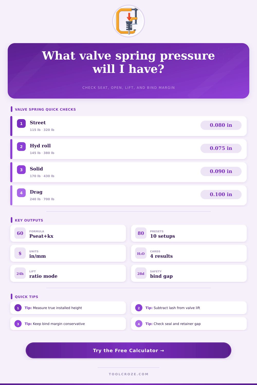
Valve spring pressure check
Calculation Breakdown
📊Current Valvetrain Snapshot
🔧Typical Pressure Ranges
| Valvetrain | Typical seat pressure | Typical open pressure | Use note |
|---|---|---|---|
| Hydraulic flat tappet street | 90 to 130 lbf | 240 to 330 lbf | Too much load can shorten cam and lifter life. |
| Hydraulic roller performance | 120 to 170 lbf | 320 to 430 lbf | Common for street roller lobes with moderate rpm. |
| Beehive or conical spring | 110 to 165 lbf | 300 to 420 lbf | Lower retainer mass can tolerate different dynamics. |
| Solid flat tappet | 130 to 190 lbf | 340 to 470 lbf | Check lobe and lifter supplier limits closely. |
| Solid roller racing | 200 to 320 lbf | 600 to 900 lbf | Spring life, pushrod stiffness, and rpm goal dominate. |
| DOHC bucket or follower | 45 to 110 lbf | 130 to 260 lbf | Follower ratio and installed height vary by head design. |
📐Bind and Clearance Guide
| Check | Common minimum | Preferred street target | Why it matters |
|---|---|---|---|
| Coil-bind margin | 0.050 to 0.060 in | 0.070 to 0.100 in | Prevents spring surge, heat, tolerance stack, and coil crash. |
| Retainer-to-seal clearance | 0.050 in | 0.060 to 0.090 in | Retainer or lock contact can damage guides and seals quickly. |
| Installed height tolerance | 0.005 in | 0.010 in checked | Small height changes move pressure by spring rate x shim. |
| Spring locator fit | Free movement | Controlled seat | Loose or cocked springs change effective travel and pressure. |
⚒Rocker Ratio and Lift Effect
| Cam lobe lift | 1.5 rocker | 1.6 rocker | Pressure impact at 400 lb/in |
|---|---|---|---|
| 0.300 in | 0.450 in | 0.480 in | About 12 lbf more open pressure. |
| 0.330 in | 0.495 in | 0.528 in | About 13 lbf more open pressure. |
| 0.360 in | 0.540 in | 0.576 in | About 14 lbf more open pressure. |
| 0.390 in | 0.585 in | 0.624 in | About 16 lbf more open pressure. |
🧪Measurement Reference
| Measurement | Tool | Best practice | Calculator field |
|---|---|---|---|
| Installed height | Height mic | Measure with locks, retainer, locator, and valve in place. | Installed height |
| Seat pressure | Spring tester | Test at actual installed height, not catalog height only. | Seat pressure |
| Coil bind | Spring tester | Use manufacturer bind height or verify solid height carefully. | Coil bind height |
| Net valve lift | Dial indicator | Check at retainer with final rocker, pushrod, lash, and geometry. | Valve lift or lobe mode |
💡Pressure and Clearance Tips
⚠Safety Note
Valve springs are the components that will close the valves once each opening event occur. The pressure that the valve springs provide when the valves are in both a closed and open position is critical to the proper functioning of the engines. Too little pressure from those spring can allow the valves to bounce or float.
Too much pressure from those springs will lead to a shorten of the service life of the valve seats, cam lobes, and pushrods. A valve spring pressure calculator is a tool that can help a person to determine the correct pressure that the valves should have within their spring such that there is neither too little pressure from the valve springs, nor too much pressure provided by those components. The first measurement that can be made with a pressure calculator is the installed height measurement of the valve springs.
How to Use a Valve Spring Pressure Calculator
The installed height is the distance from the spring seat to the underside of the retainer of the valve spring when the valve is in its closed position. Any error in the installed height will lead to errors in the seat pressure that is calculate by the valve spring. This value can be entered into the calculator, and the calculator will reflect how the installed height impacts the spring’s total pressure.
The spring rate is the next variable that need to be considered in the calculation. The spring rate is the amount of pounds (or newtons) of spring force that the valve spring creates for every inch (or millimeter) that the spring is compressed. The spring pressure calculator uses this value to mathematically compute the spring’s total pressure at full valve lift.
The third measurement is the net valve lift. This is the total distance that the valve will travel from its closed position. It is possible that this value is not the same than the cam lobe lift, especially if rockers are utilized in the engine.
The spring lift can be calculated by multiplying the cam lobe lift by the rocker ratio, and subtracting lash and deflection from that spring. Another parameter that needs to be considered is the coil bind height. Coil bind is the height at which the valve spring’s coils begin to touch each other.
Any travel of the valves beyond this height will cause damage to the engine components. Subtracting the bind height from the open height will reveal the remaining travel of the valve springs. Using a safety margin is necessary for this component of the spring calculation.
The safety margin ensure that the valve springs do not reach coil bind at too high of a rpm. Retainer-to-seal clearance is another measurement of the valves that should be monitored. If the lock or retainer touches the seal at full lift, then this clearance has been lost.
This parameter will reveal how much travel remains before the retainer touches the seal. If the retainer touches the seal, the numbers will be zero or negative. In such cases, the height of the valve spring is too great or the seal is too low; a different seal or locator can be used.
Target seat pressure and target open pressure are the next parameters that can be entered into the spring pressure calculator. The target seat and open pressures can be entered into the calculator, and the calculator will calculate the thickness of the shim that would be required to achieve these valves’ targets. Adding shims will lower the installed height.
Lowering the installed height will increase the seat and open pressure of the valve springs. Removing shims will increase the installed height of the valve spring. Increasing the installed height will lower the spring’s pressure.
Reference tables can be used to provide information about the valve spring pressures that are typically used in various types of engines. For instance, hydraulic flat tappet engines have lower seat pressures because the cam and lifter are already taking the load. Solid roller engines have higher seat pressure because they run at much higher rpms.
Beehive springs are in the middle of these two types of engines because there is less inertia of the smaller retainer. Common errors in measuring the valves include not measuring the installed height with the locks and retainer in place. Additionally, another common error is using the bind height from the spring catalog rather than actually measuring the spring on a spring tester.
These incorrect measurements cannot be corrected by the spring pressure calculator, but the calculator will reveal the impact of entering incorrect data. Rocker ratio changes will impact the valve lift, and thus, the pressure calculations. For instance, changing the rocker ratio from 1.5 to 1.6 will increase the valve lift by 6%.
The impact can be seen immediately in the spring pressure calculator to allow for the recognition of any possible incompatibility between the cam and valve springs. The decision of the desired pressure for the valve springs involves a tradeoff of several components. Higher seat pressure is required to control the valves at high rpm, but will create more friction at idle and low rpm.
High open pressure will keep the valve on the seat during the overlap portion of the engine cycle, but can shorten the life of the springs if too aggressive. These tradeoffs can be easily considered when using the spring pressure calculator, since it removes the need for computations. The smallest valve spring pressure that can be utilized is that which ensures the valve maintains contact with the cam across the range of engine rpms that are used.
Any margin has to be provided for manufacturing tolerances of the engine components. Each of these parameters can be understood and each warning can be properly considered before making the adjustments needed to the valve spring system. What are the variables that need to be considered in the use of a valve spring pressure calculator?
Valve spring pressure calculators ask for several different measurements of the engine and its valve springs. Each of these variables is essential to calculating the total pressure that will be created by the valve spring. The first variable is the installed height of the valve springs.
This is the distance from the spring seat to the underside of the retainer of the valve spring when the valve is in its closed position. Any error in the installed height will lead to errors in the seat pressure of the valve spring. This measurement can be entered into the calculator, and the calculator will indicate how the installed height may impact the spring’s total pressure.
The second variable is the spring rate of the valve springs. The spring rate is the amount of pounds (or newtons) of spring force that is created by the valve spring for every inch (or millimeter) that the spring is compressed. This value is used by the spring pressure calculator to mathematically compute the spring’s total pressure.
The third variable is the net valve lift. This is the total distance that the valve will travel from its closed position. Often, this is less than the lift of the cam’s lobes.
The spring lift can be calculated by multiplying the cam lobe lift by the rocker ratio, and subtracting lash and deflection from that spring. Another parameter that needs to be considered is the coil bind height. Coil bind is the height at which the valve spring’s coils begin to touch each other.
Any travel of the valves beyond this height will cause damage to the engine components. Subtracting the bind height from the open height will reveal the remaining travel of the valve springs before the coils begin to bind with each other. Target seat pressure and target open pressure are two variables that may be entered into the spring pressure calculator.
These targets can help indicate the thickness of the shim that will be required to achieve the target spring pressures. Adding shims will lower the installed height. Lowering the installed height will increase the seat and open pressure.
Removing shims will increase the installed height. Increasing the installed height will lower the spring’s pressure. Reference tables ask for information about the type of engine that is to be built.
For instance, hydraulic flat tappet engines have lower spring pressures because the cam is already taking some of that load. Solid roller engines have higher spring rates because they tend to operate at much higher rpms. Beehive springs are in the middle of these two types of engines.
Common errors when using valve spring calculators include incorrect measurements of the installed height of the valve spring. For example, not measuring with the retainer and locks in place will lead to incorrect calculations of the spring pressure. Additionally, another common error in using spring calculators is using the bind height from the spring catalog rather than actualy measuring the spring itself on a spring tester.
These errors will not be corrected by the calculator, but it will indicate errors if they are entered into the calculator. Another variable to consider is any changes to the rocker ratios of the engine. Changing the rocker ratios will impact the net lift of the valves.
For instance, changing the rocker ratio from 1.5 to 1.6 will increase the valve lift by 6%. The impact of this change can be seen in the spring pressure calculator to determine if the cam lobe is compatible with the valve springs. Finally, another tradeoff will be made in determining the desired spring rate of the valves.
Higher spring rates will allow the engine to maintain high rpm with proper control of the valves, but will increase the friction of the engine at idle and low rpms. High open spring rates will help to ensure that the valves remain on the seat during the overlap portion of the engine cycle, but will shorten the life of the valve springs if they are too aggressive. The smallest spring rates that can be utilized is that which ensures the valve maintains contact with the cam across the range of rpms at which the engine will be used.
Additionally, some margin has to be provided for the tolerances of the engine components to be manufactured. Finally, once the user understands each of the parameters of the valve spring calculator, such as what each parameter represents, and what warnings are presented, the decision of what that user will adjust in the engine is up to the user and their experience with valve spring calculations.