Torsion Spring Calculator
Estimate torsion spring torque, angular rate, leg force, corrected bending stress, spring index, and safety factor from wire diameter, mean coil diameter, leg length, active coils, angle deflection, and material modulus.
Load a common shop mechanism, then adjust the spring geometry, leg length, deflection angle, modulus, preload torque, and stress limit.
Calculation Breakdown
| Material | Elastic modulus | Screen stress | Typical torsion use |
|---|---|---|---|
| Music wire ASTM A228 | 30.0 Mpsi / 207 GPa | 190 ksi / 1310 MPa | Clips, latches, precision shop springs |
| Hard drawn spring wire | 29.0 Mpsi / 200 GPa | 125 ksi / 860 MPa | Light hardware returns and general mechanisms |
| Oil tempered wire | 29.5 Mpsi / 203 GPa | 150 ksi / 1035 MPa | Rugged levers, guards, and door returns |
| Chrome silicon A401 | 30.0 Mpsi / 207 GPa | 210 ksi / 1450 MPa | Higher stress cycling and shock duty |
| 302 stainless steel | 28.0 Mpsi / 193 GPa | 130 ksi / 895 MPa | Corrosion resistant clips and covers |
| Phosphor bronze | 15.0 Mpsi / 103 GPa | 70 ksi / 480 MPa | Electrical contacts and nonmagnetic parts |
| Check | Preferred range | Warning sign | Why it matters |
|---|---|---|---|
| Spring index C = D / d | 4 to 14 | Under 4 or over 14 | Controls forming difficulty and stress correction |
| Active coils | 3 to 12 body coils | Too few or crowded coils | Small coil-count errors strongly change rate |
| Leg length | Long enough for stable force | Short arm, high tip force | Force equals torque divided by moment arm |
| Angle deflection | Within supplier max angle | Coils touch or legs foul | Large rotation increases torque and stress |
| Winding direction | Load tightens body coils | Load unwinds body coils | Unwinding can loosen body fit and change preload |
| Application | Typical wire | Working angle | Design note |
|---|---|---|---|
| Small clip spring | 0.030 to 0.055 in | 20 to 60 deg | Check leg bend radius and contact force |
| Cabinet hinge assist | 0.062 to 0.105 in | 45 to 100 deg | Use paired springs when load is off center |
| Machine guard return | 0.080 to 0.148 in | 60 to 120 deg | Verify stop position and trapped energy |
| Foot pedal return | 2.0 to 4.0 mm | 35 to 90 deg | Confirm ergonomic force at the pedal pad |
| Heavy access door | 0.125 to 0.250 in | 30 to 90 deg | Use guarded stops and rated shafts |
| Output | Formula | Inputs | Meaning |
|---|---|---|---|
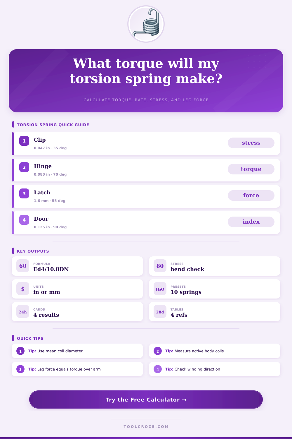
| Angular rate | k = E d^4 / (10.8 D N) | E, d, D, N | Torque per radian for a round-wire torsion spring |
| Torque | T = preload + k theta | Rate, angle | Moment at the spring body after rotation |
| Leg force | F = T / L | Torque, leg length | Approximate force at the load point on the leg |
| Index | C = D / d | Mean diameter, wire | Coil proportion and manufacturability check |
| Stress | S = Ki 32 T / (pi d^3) | Torque, wire, Ki | Corrected bending stress in the spring wire |
Torsion springs are found within various mechanism. Furthermore, torsion springs work more differently than extension or compression. Instead of extension or compression, torsion spring work by twisting one leg of the torsion spring relative to the other leg of the torsion spring.
The result of this twisting motion allow the torsion spring to push back against the device that is twisting the spring. Because of this action, torsion springs are found in items like clothespins, garage doors, and foot pedal. The amount of torque that a torsion spring will create is based off several measurement of the torsion spring.
Torsion Springs: How They Work and What to Check
For example, factor like the wire diameter of the torsion spring, the mean coil diameter, the number of active body coils, and the length of the legs of the torsion spring will impact the amount of torque that the torsion spring creates. As a result of these parameters all having an impact upon the amount of torque that is created, changing any of those parameter will change the amount of torque that the torsion spring creates. Additionally, you can use a calculator to determine the torque that the torsion spring will create.
Furthermore, the calculator can also report whether the stress levels of the torsion spring are within safe limits. More specifically, the calculator accounts for the tightness of the coils in relation to the thickness of the wire of the spring. Another important parameter of torsion springs is the spring index.
The spring index is a ratio of the mean diameter of the torsion spring to the wire diameter of the spring. The spring index is important in that it will impact the difficulty of forming the torsion spring, as well as the stress that will act upon the torsion spring. For torsion springs, the spring index typically ranges between 4 and 14.
If the spring index is less than 4, the wire will bend excessive and fight against itself during the forming of the spring. If the spring index is greater than 14, the body of the torsion spring will be floppy and the spring may move out of place when the legs of the spring are moved. The calculator for torsion springs can report these limits so that you can adjust the spring before you order your materials.
Another factor in the creation of torsion springs is the material that are utilized. For example, many torsion springs are made of music wire because music wire is strong for its cost. Additionally, stainless steel is another common material for torsion springs, especially if the torsion spring will be exposed to wet environment or when it will be used outdoors.
Yet other factors to consider with the spring include the duty cycle of the torsion spring and how much stress the spring will experience. For instance, static application of torsion springs can better take high stress ratios than torsion springs that are constantly being cycled. The length of the legs of the torsion spring will impact the force of the spring at the contact point.
In other words, you can find the force at the contact point by dividing the torque of the torsion spring by the length of the legs. The longer the legs of the torsion spring, the less force that will be required to operate the device that include the torsion spring. The longer the legs, the further that the tip of the leg will travel in an arc.
Additionally, if other components of the device are close to the torsion spring, the leg of the torsion spring may contact those other components before the leg of the spring reaches the desired angle. The calculator will report both the force of the leg and the arc length that the leg will travel so that you can consider both of these measurements prior to cutting the torsion spring. Another factor to consider is the winding direction of the torsion spring.
The winding direction will impact the tightening of the coils of the spring. For example, if the torsion spring is wound in the opposite of the winding direction that the spring manufacturer indicates for the spring, the coils will loosen from the shaft of the spring. Such loosening will impact the performance of the spring.
The calculator can account for the winding direction of the spring to make certain that the spring manufacturer will wind the coils in the indicated direction when the spring is manufactured. Errors in the creation of torsion springs often result from incorrectly counting the coils or measuring the diameter of the spring. For example, some people include the leg bends in the count of the coils of the spring.
Additionally, the outside diameter of the spring may be measured rather than the mean diameter. These type of errors will lead to inaccurate calculations of the amount of torque of the torsion spring. The calculator cannot account for incorrect measurement, but it can report the impact of such errors.
The performance of a torsion spring may differ between the ideal formula of the spring and its performance within the actual device. For example, the fit of the shaft of the spring, the support of the end of the spring, and even the temperature within which the spring operates will impact the performance of the spring. A torsion spring that works within the ideal conditions for the spring may not function within the actual device.
For this reason, it is common for those who build devices that incorporate torsion springs to test a sample of the spring within the device prior to initiating the production of the device that incorporates such torsion springs. It is also important to include some margin of safety within the design of a torsion spring. For example, the design margin for torsion springs can be used to introduce an extra load into the spring that is calculated.
Such a load will account for the springs capacity to handle failure. Additionally, torsion springs are considered to be potentially dangerous in the case of sudden release of the energy that is stored within the spring. Therefore, using guarded stops, proper shaft sizing, and stress ratios will prevent the sudden release of the energy within the spring.
The values of the torsion spring for torque, stress, and force can be used to determine if the torsion spring is an appropriate spring for the given device. In addition to these calculations, the creation of a prototype of the device will help ensure that the torsion spring will perform as expected. Thus, using both the calculation and the prototype of the spring will help to ensure that the torsion spring that is to be manufactured is a reliabel component of the device.