Tapping threads by hand or tapping threads on an machine can be difficult. Taps can cut clean threads or the tap can snap inside the work piece’s hole. The speed at which the tap turn and the movement of the metal chips are important element in the tapping process.
Many machinists use speed and feed chart to help them remember the proper speeds and feed rates for taps of specific size and for specific types of metal. Speed and feed charts isnt decorative. They provide the numbers for the speeds and feed rate for taps.
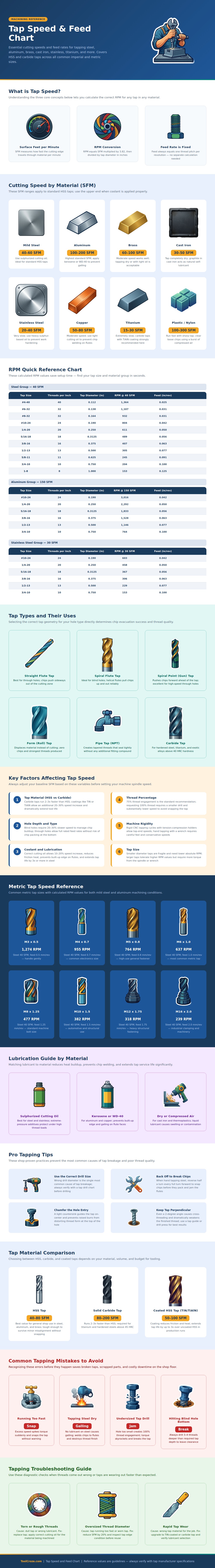
How to Set Tap Speed and Feed for Different Metals
The numbers on the charts ensure that the tap stay sharp and that the tapping process create threads that remain accurately. The charts use a value called surface feet per minute (SFM) to determine the rate at which the tap edge move through the work piece during one minute. Based off the SFM and the diameter of the tap, the machinist can calculate the correct number of RPMs for the tap.
The feed rate can also be determined with the tap size, but the calculation for the feed rate is more simple than calculating the RPMs for the tap. The feed rate for taps is the same than the thread pitch for the tap, the machine must be adjusted to move at the same rate as the pitch of the threads to be created. The speed and feed chart allow the machinist to move from the material to the correct RPM.
There is no guessing involve about the correct speed for a given tap. The type of metal to be tapped influence the speed at which the tap turns. Metals react to speed differently.
Aluminum will allow taps to turn at high speeds due to the ease with which aluminum is cut and how well it conduct heat away from the tap. However, steel should be tapped at slower speeds to prevent the metal from work hardening and to prevent build up of metal chips on the tap flutes. Stainless steel will work best at even slower speeds then steel to avoid the metal work hardening and chips welding to the tap’s cutting edges.
Cast iron require taps to turn slowly, the graphite in the material acts as a lubricant for the tap. Finally, the machinist should use the slowest speeds for titanium metals, the metals are both strong and poor conductor of heat, so if the tap is pushed to high speeds when tapping titanium metals, the tap will overheat before it can complete the hole. Speed and feed charts also separate the speeds for different tap style.
The flow of metal chips when tapping is important. For instance, straight flute taps are used to create through holes because the chips has a place to go out of the work piece ahead of the tap. However, the machinist uses spiral flute taps in blind holes because the spiral flute help to pull the chips out of the blind work piece.
Spiral point taps create strong threads at high speeds for through holes. Finally, form taps do not cut the material being tapped; rather the form taps push the metal sideways to create strong threads. Although no chips are created when using form taps, the size of the drill bit needs to be different than taps that create chips.
If the wrong type of tap is use for the type of hole, the tap may get jammed in the work piece. Several factor other than the metal to be tapped can influence the rates at which a tap should turn. For example, carbide taps will reach higher RPMs than high-speed steel taps due to the heat resistance of carbide tools.
Taps with titanium nitride (TiN) coatings will work at higher RPMs due to the reduced friction between the tap and the work piece. The quality of coolant for the work piece will allow taps to turn at higher RPMs; proper cutting oil will allow RPMs to increase by ten or twenty percent; proper cutting oil will also reduce the chance of galling. Another variable to consider is the percentage of the threads that should be engaged.
Most shops set their taps to seventy-five percent of the total depth of the thread; if they attempt taps to reach full thread depth, they will need to use a smaller drill and require higher amount of torque; tapping to full thread depth will increase the chance of snapping the tap. Another variable that enters into the equation is whether the work piece has a blind or through hole. Work pieces with blind holes have an extra depth dimension to allow for the chips to exit the blind work piece.
The speed at which taps are used for blind holes is lower than taps used in through holes. Through holes are more forgiving of the tapping process. Finally, the rigidity of the machine can impact the RPMs of the tap.
For instance, a CNC machine will allow the tap to turn at high speeds compared to hand taps. Small mistake in the tapping process can lead to significant problems with the tap. Using high speeds for taps can lead to the tap snapping due to increased torque.
If the drill bit is too small for the diameter of the hole to be tapped, the tap will break. If high speeds are attempted on steel without the use of lubricant, chips will weld to the tap and ruin the tap and the created threads. Finally, if taps are used in blind holes, the tap may reach the end of the blind hole, causing the tap to break.
Using a speed and feed chart remove the guessing game from the tapping process. The machinist must start with the work piece material and the type of tap. Then, the machinist can adjust the chart for the type of coolant that will be used and the type of machine setup.
Once these values have been determined, the machinist can set the RPMs of the tap. Thus, there is no mystery to the tapping process; there are only a few factor to consider, and the machinist is rewarded for their attention to detail to the tapping process.
