Spring Design Calculator
Check a helical compression spring from target load, deflection, wire diameter, mean coil diameter, active coils, material shear modulus, stress, spring index, and safety factor.
| Material | Shear modulus | Static allowable | Typical use |
|---|---|---|---|
| Music wire ASTM A228 | 11.5 Msi / 79.3 GPa | 130 ksi / 896 MPa | General precision springs |
| Hard drawn ASTM A227 | 11.5 Msi / 79.3 GPa | 95 ksi / 655 MPa | Light duty hardware springs |
| Oil tempered ASTM A229 | 11.2 Msi / 77.2 GPa | 110 ksi / 758 MPa | Shock and medium duty springs |
| Stainless 302 | 10.0 Msi / 69.0 GPa | 100 ksi / 690 MPa | Corrosion resistant springs |
| Chrome silicon A401 | 11.2 Msi / 77.2 GPa | 150 ksi / 1034 MPa | High stress cyclic springs |
| Phosphor bronze | 6.0 Msi / 41.4 GPa | 60 ksi / 414 MPa | Electrical and nonmagnetic uses |
| Check | Preferred range | Low warning | High warning |
|---|---|---|---|
| Spring index C = D / d | 4 to 12 | Under 4 is hard to form | Over 12 may buckle or tangle |
| Wahl factor | About 1.05 to 1.40 | High correction means tight coils | Low correction means easier stress |
| Active coils | 3 to 20 | Too few can be nonlinear | Too many may buckle |
| Safety factor | 1.5 static, 2+ cyclic | Below target needs redesign | Very high may be oversized |
| Application | Typical load | Deflection range | Design note |
|---|---|---|---|
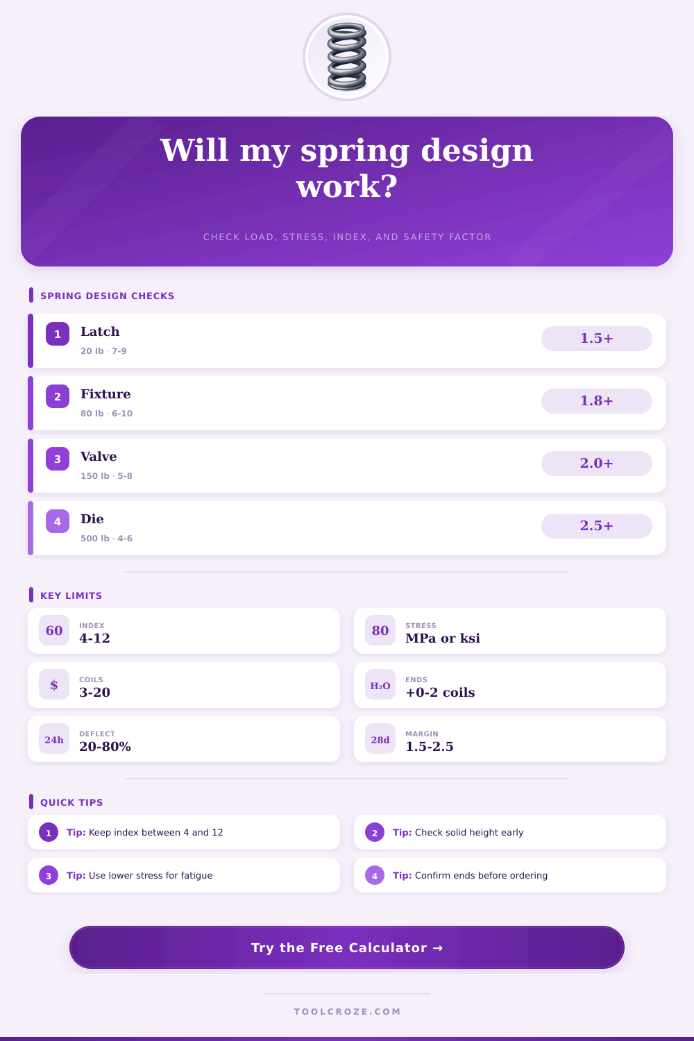
| Latch return | 5 to 30 lb | 0.25 to 0.75 in | Keep friction low and index moderate |
| Fixture clamp | 40 to 150 lb | 0.5 to 1.5 in | Check stress after adding preload |
| Valve return | 20 to 200 lb | 0.1 to 0.75 in | Use fatigue margin for cycling |
| Die stripper | 200 to 800 lb | 0.25 to 1.0 in | Watch solid height and guide fit |
| Output | Formula | Inputs | Meaning |
|---|---|---|---|
| Spring rate | k = Gd^4 / (8D^3Na) | G, d, D, Na | Force required per unit travel |
| Load | F = kx | Rate, deflection | Predicted working force |
| Spring index | C = D / d | Mean diameter, wire | Coil manufacturability indicator |
| Wahl factor | Kw = (4C-1)/(4C-4) + 0.615/C | Spring index | Curvature stress correction |
| Shear stress | tau = Kw 8FD / (pi d^3) | Load, diameter, wire | Corrected torsional wire stress |
| Safety factor | SF = allowable / tau | Material, duty, stress | Static design margin estimate |
Designing a spring requires consideration of many different variables that interact with one another during the spring design process. The type of application in which the spring will be used can range from a latch return to a valve plunger. Each of these different applications require consideration of different factor.
Prior to calculating the mathematical variables of the spring, it is necesary to decide what the spring need to do. Springs store energy through the twisting of wire into a helix shape. The amount of force that a spring can deliver is dependent upon the thickness of the wire that is used to create the spring, the spacing of the coils, and the resistance to shear of the metal that is utilized in the creation of the spring.
How to Design a Spring
Each of these factors is mathematicalley connected to the other factors, so altering one will mathematically alter the others. A spring calculator can be used once the target load and deflection of the spring have been determined. By plugging the geometry of the spring into the calculator, you can see the amount of force that the spring will provide.
Wire diameter is one of the main factor that must be considered in spring design. The stiffness of the spring is related to the diameter of the wire to the fourth power. Therefore, increasing the diameter of the spring will also increase the amount of stress that act upon the spring.
Springs designers must take these two factor into consideration together. The Wahl correction accounts for the extra stress that the curvature of the spring coils places upon the spring. Without this correction, the spring would of been calculated to have an optimistic stress level that would have led to potential design errors.
The second main factor to consider within spring design is the mean coil diameter of the spring. The spring index of a spring is the mean coil diameter divided by the wire thickness. Indices that are below 4 are difficult to wind when manufactured.
Coils with indices above 12 have an increased chance of buckling or tangling with other manufactured parts. Indices should be within this range to ensure that the spring is manufacturable: between 4 and 12. The spring calculator will alert the designer if the index is outside of this range.
Active coils play a crucial role in the spring in that the number of active coils will mathematically change the travel of the spring. Fewer active coils will create a stiffer spring that has less margin for buckling. More active coils will lead to a softer spring with more margin for buckling.
This parameter can be entered into the spring calculator so that the spring will exhibit the desired spring rate. Another factor that impacts spring design is end condition. Spring ends that are closed and ground will add two inactive coils to the spring and will sit flatter than springs with plain ends.
Plain ends are cheaper to produce. The solid height of the spring will be affected by the end condition. Ensuring that the spring has clearance from other manufactured parts is essential to ensure that the spring will not be forced to its solid height.
The solid height of the spring will determine if the spring will reach the solid height of the spring during operation. Material choice impacts spring design. Music wire is a common material that is used for springs.
The material is very strong. Alternatively, stainless steel will resist corrosion but will have a lower shear modulus. Because the shear modulus is lower, stainless steel will have a softer spring rate than music wire.
Chrome silicon is a material that can withstand higher levels of stress. The stress that is allowed in the spring will alter depending on the duty cycle of the spring. For springs that experience thousands of cycles of compression, the allowable stress will be lower than that for springs that are static in position.
In designing a spring to endure thousands of cycles, the designer will adjust the allowable stress to reflect this duty cycle. The safety factor will be applied to the spring after the adjustment to the stress that is allowed for springs with this duty cycle. A safety factor of 1.5 is typically used for springs that are static in use.
For springs that are cycled thousands of times, a safety factor of 2.0 is used. Any safety factor that is less than the minimum that is required for the spring will be indicated to the designer with a status message within the spring calculator. In reality, there are many physical factors that act upon a spring that cannot be accounted for in the equations that are used in spring design.
Springs that are slender or have a low spring index may buck under a given load. If the spring is not manufactured with plain ends, side loads can be placed upon the spring that will create bending of the spring. These types of loads are not accounted for in the formulas for compression springs.
The effect that temperature will have upon the spring can also be accounted for in the design process. The surface treatment of the spring has an effect upon the life of the spring. These factors are not accounted for in the spring calculator.
The spring design process is simple. Begin with the load that must be applied to the spring and the travel of the spring. Select the material that will best suit the environment in which the spring will be used.
Enter the spring wire size and coil diameter into the spring calculator to determine the number of active coils that the spring should have. Adjust the spring parameters until the safety factor and spring index are within the limits that is desired for the spring. Ensure that solid height of the spring is accounted for and will not create clearance issues with other manufactured parts.
When all design parameters are within the desired limits, the spring is ready to be quoted for manufacturing.