Sine Vise Calculator
Calculate gauge block stack height, total setup height, actual sine vise angle, angle error, and shim correction from center distance and target angle.
⚙Named Machining Presets
Load a common sine vise, sine bar, or inspection setup, then adjust the center distance, target angle, actual gauge stack, and tolerance for your shop standard.
📏Sine Device, Gauge Stack, and Error Inputs
Use the certified center distance stamped on the sine vise or bar.
Enter the stack you plan to wring and place under the raised roll.
Optional riser, parallel, or setup block below the gauge stack.
Used to show rise over a part, comparator sweep, or test indicator travel.
Optional measured rise for checking a machined angle or setup sweep.
Sine vise setup result
📊Current Setup Summary Grid
📐Common Sine Stack Reference
| Target angle | 5 inch center distance | 10 inch center distance | 100 mm center distance | Setup note |
|---|---|---|---|---|
| 1 deg | 0.0873 in | 0.1745 in | 1.745 mm | Fine tilt, very sensitive to dust and burrs. |
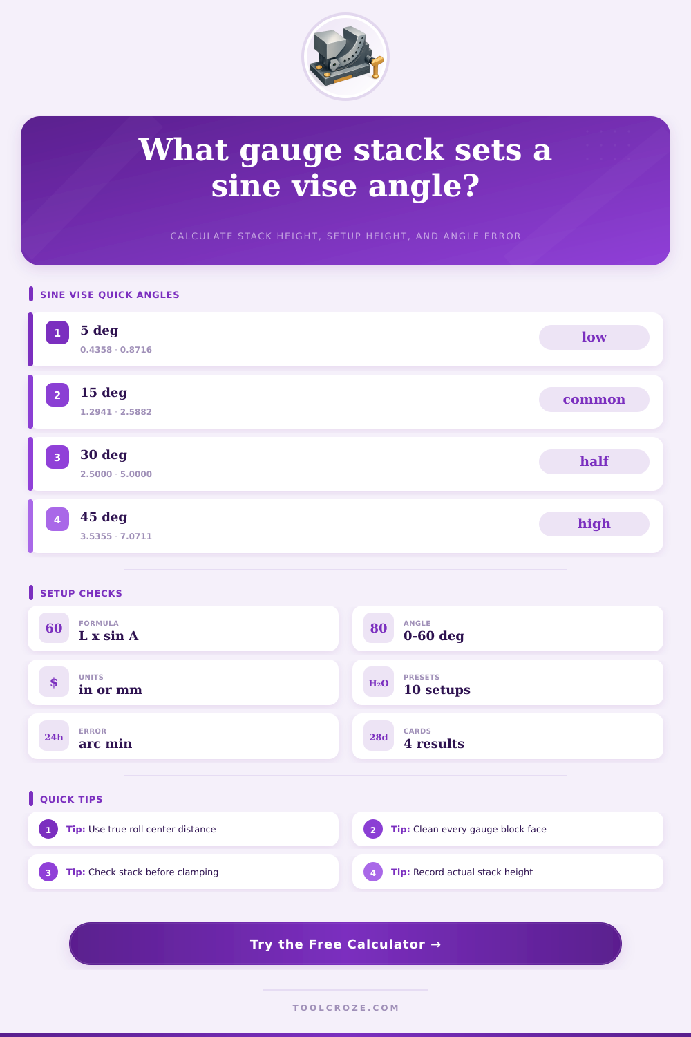
| 5 deg | 0.4358 in | 0.8716 in | 8.716 mm | Common for shallow relief and inspection sweeps. |
| 7.5 deg | 0.6526 in | 1.3053 in | 13.053 mm | Useful for small fixture angles and tapers. |
| 15 deg | 1.2941 in | 2.5882 in | 25.882 mm | Comfortable height on most sine vises. |
| 22.5 deg | 1.9134 in | 3.8268 in | 38.268 mm | Half of 45 degrees, common on toolroom fixtures. |
| 30 deg | 2.5000 in | 5.0000 in | 50.000 mm | The sine is exactly one half of center distance. |
| 45 deg | 3.5355 in | 7.0711 in | 70.711 mm | High stack, verify support and clamping clearance. |
| 60 deg | 4.3301 in | 8.6603 in | 86.603 mm | Near upper practical range for many sine plates. |
🧮Gauge Block Planning Table
| Planning item | What to enter | Calculator use | Shop check |
|---|---|---|---|
| Center distance | Certified roll center spacing | Sets the sine formula length | Use stamped value, not overall vise length. |
| Exact stack | Center distance times sine angle | Main required gauge height | Build from clean wrung blocks. |
| Actual stack | Gauge stack you can assemble | Finds actual angle and error | Record actual stack on the job sheet. |
| Base height | Parallel, riser, or spacer under stack | Adds total setup height | Keep spacer flat and fully supported. |
| Gauge increment | Smallest available step | Shows planned rounded stack | Use smaller increments for small angles. |
| Thermal change | Temperature change from reference | Estimates stack growth | Allow blocks and fixture to stabilize. |
⚒Angle Error and Sensitivity Table
| Condition | Approximate effect | Best correction | Practical note |
|---|---|---|---|
| 0.0001 in stack error on 5 in centers | About 0.07 arc minutes | Add or remove tenths blocks | Effect grows slightly at steeper angles. |
| 0.001 mm stack error on 100 mm centers | About 0.03 arc minutes | Use metric inspection blocks | Small but visible in high accuracy grinding. |
| Dirt under lower roll | Acts like stack height error | Stone and clean contact points | One chip can dominate the math. |
| Wrong center distance | Proportional stack error | Use certificate value | Do not substitute nominal vise length. |
| Overhanging heavy work | Can deflect the setup | Support and clamp near cut | Indicate after clamping when possible. |
| Thermal growth | Stack changes with temperature | Stabilize blocks and work | Most important on long stacks. |
🔧Preset Setup Reference
| Preset | Device | Center distance | Target angle | Typical use |
|---|---|---|---|---|
| 5 in Vise 15 Deg | Sine vise | 5.0000 in | 15 deg | Relief milling, grinding, and inspection. |
| 5 in Vise 30 Deg | Sine vise | 5.0000 in | 30 deg | Common fixture and dovetail reference angle. |
| 10 in Bar 7.5 Deg | Sine bar | 10.0000 in | 7.5 deg | Long workpiece taper setup. |
| 100 mm Toolroom 12 Deg | Metric sine vise | 100.000 mm | 12 deg | Metric toolroom milling and grinding. |
| 200 mm Plate 22.5 Deg | Sine plate | 200.000 mm | 22.5 deg | Large plate work with stable support. |
| Fine Tilt 1 Deg | Inspection setup | 10.0000 in | 1 deg | Small taper check where tiny stack errors matter. |
ℹSetup Tips and Safety
A sine vise or a sine bar is a tool that allows a person to hold a workpiece at a specific angle. A gauge block can be used to allow the tool to achieve a specific angle. To achieve this specific angle, gauge blocks is placed under one roll of the sine vise or sine bar.
The gauge blocks will allow the sine vise or bar to tilt to the angle that is required for the workpiece. The measurement for a sine vise or bar can be calculated with a calculator. The calculator will provide the user with the required measurements for the height of the gauge block stack, the total height that the stack will achieve, the actual angle that the specific gauge block stack will create, and the error that may result from the actual angle of the gauge blocks compared to the targeted angle.
How to Use a Sine Vise and Gauge Blocks to Set Angles
The center distance are a critical component for the sine vise or bar, as it is an essential component of the formula that determines the angle of the tool. You can find the center distance by examining the tool for a stamped distance. Most sine vises has a center distance of 5 inches or 10 inches.
Many metric sine bars will have the center distance stamped in millimeters. Using this value stamped on the sine vise or bar will ensure that the calculations for setting up the gauge blocks is accurate. The target angle for the workpiece is another critical measurement for the calculator.
The print that contains the specifications for the workpiece can determine the target angle. If the center distance and the target angle for the workpiece are entered into the calculator, the calculator will calculate the height of the gauge block stack that is required to create the target angle. Gauge blocks are sold in specific heights.
It is impossible to find a set of gauge blocks that will achieve the height calculated by the calculator. The heights of gauge blocks are specific and may be very small in measurement. In order to use the gauge blocks, the user must round the calculated height up or down to the closest gauge block height.
By rounding the height of the gauge block stack to the nearest height available for purchase, the angle that is created will change slightly from the target angle. The calculator will provide an error in arc minutes, which will allow the user to understand the difference between the target angle and the actual angle that will be created. If the error value is small, it may be acceptable to allow for the change in angle.
If the error value is significant, it may be necessary to find another set of gauge blocks or to make an adjustment to the workpiece after it is clamped to the sine vise or bar. The actual stack field is helpful for those on the shop floor. The user can enter the height of the actual gauge block stack into this field in the calculator.
The calculator can determine the angle that will be created with these gauge blocks. Additionally, the difference between this actual angle and the target angle can be provided in arc minutes. This value can be compared to the tolerance of the workpiece for that angle.
If the error is within the tolerance, the workpiece can be begun. If the error is outside of the tolerance, it will be necessary to add or remove gauge blocks from the sine vise or bar prior to beginning work. Heat will impact the gauge blocks.
As the temperature of the gauge blocks increases, the metal will expand. A tall stack of gauge blocks placed near a warm machine or near a warm light will expand in height. As the height of the gauge block stack changes, the angle of the sine vise or bar will change.
The change in angle will be in arc minutes, and the arc minutes may be more than one. The calculator allows for the user to enter the temperature change and the expansion coefficient of the gauge blocks to determine the impact that temperature can have on the angles of the sine vise or bar. The thermal growth will have a small impact on the gauge blocks in most shops.
However, it is possible for the temperature change throughout the day to have an impact on the angles that the sine vise or bar sets up. A reference table can include the angles that are commonly used on the shop floor and the gauge block height that is required for each of those angles. The reference table can include different center distances for the sine vise or bar.
These reference tables are not to be used as a replacement for the calculator, but they can act as a quick check for the workpiece and the tolerances for the angles. For instance, a fifteen degree angle at five inch centers will require a gauge block height of slightly less than one and three tenths of an inch. A thirty degree angle will require a gauge block height that is double the height of the fifteen degree angle.
A forty five degree angle will require a gauge block height that is more than three and a half inches. Additionally, if the height of the gauge block stack is set to a tall height, it may be necessary to add support for the gauge blocks or to ensure that the clamps have clearance for the tall gauge block stack. A benefit of using a sine vise or bar is that the mathematics involved in setting up the gauge blocks is simple, even for workpieces that are complex in nature.
The angle that is set up on the sine vise or bar is independent of the workpiece that is being created. Once the angle is set up on the sine vise or bar, the cutter or grinder will follow that angle. Because of the simplicity of using a sine vise or bar to create angles in workpieces, they are common in the shops.
In cases where the angle of the workpiece has been created, the indicator sweep length and the rise that is measured with the indicator can be used to determine if the angles are within the required tolerance. By sweeping the indicator across a known length of the workpiece, the user can measure the rise of the indicator. Based on this reading, the calculator will determine the angle of the workpiece.
Additionally, it will report the error in arc minutes in relation to the target angle. The logic used to calculate the angle is the same as for a dovetail or a tapered feature. The length that is swept by the indicator represents the opposite side of a right triangle, and the rise of the indicator represents the adjacent side of that right triangle.
The angle that is calculated will indicate if the feature is within the required tolerance. Common mistakes when using a sine vise or bar include using the wrong center distance for the workpiece or using gauge blocks that are not free of metal chips. Metal chips that are placed under one of the rolls of the sine vise or bar will act as extra height for the gauge block stack.
Any burrs on the gauge blocks will also introduce an error into the height of the gauge block stack. The calculator will not detect these errors. However, it will allow the user to understand how small the error must be to ensure that the workpiece remains within the tolerance.
For instance, if the tolerance is two arc minutes, a height error of one tenth of a thousandth of an inch will be significant. Any surfaces that will be in contact with the gauge blocks or the rolls of the sine vise or bar must be very clean. Another important field for the user is the angle tolerance field.
If the tolerance for the angle of the workpiece is loose at five arc minutes, this may be sufficient for the workpiece. However, if the workpiece is to have angles that are ground or inspected, the tolerance may have to be much smaller. The status for the workpiece will show either green, yellow, or red based on the error in arc minutes for the workpiece angle.
Green will mean that the angle is within the tolerance. Yellow will mean that the angle may be within the tolerance but should be checked again. Red means that the angle is outside of the tolerance and the workpiece should not be begun.
The value of using a sine vise or bar is that it allows for the next workpiece to have the same angle as the first workpiece. The calculator allows the user to turn the variables into numbers that can be entered into the calculator to determine if the gauge blocks will create the required angle. The calculator can be used to determine if the setup will produce the angle that is required for the workpiece.
By determining these numbers, the workpiece can be set up correctly and the work can begin. In order for the workpiece to maintain the same angle, the gauge blocks must remain clean. Additionally, the user must ensure that the setup is complete before beginning work on the workpiece.