Weld Capacity Calculator
Estimate weld load capacity from weld type, effective length, effective throat, electrode strength, load angle, safety factor, joint efficiency, and practical inspection factors.
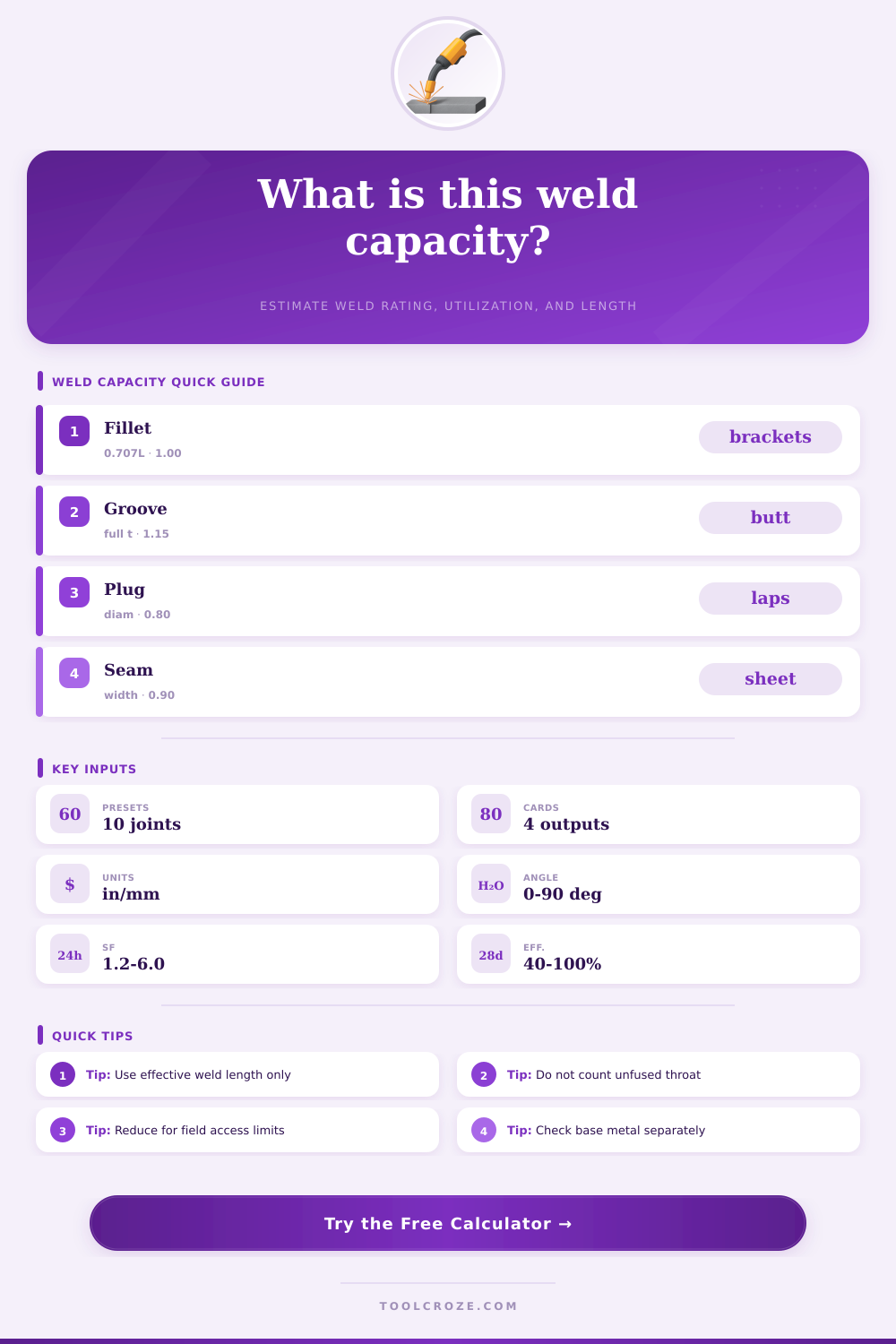
Choose a common shop or field joint. Each preset fills the weld type, dimensions, strength, load, angle, safety factor, and joint efficiency.
| Weld type | Typical throat input | Model factor | Primary caution |
|---|---|---|---|
| Fillet weld | 0.707 x equal leg size | 1.00 | Base metal tear-out and eccentricity can govern. |
| Full penetration groove | Fused member thickness | 1.15 | Qualification and inspection level must match the assumption. |
| Partial penetration groove | Qualified effective throat | 0.95 | Do not count unqualified root penetration. |
| Plug or slot weld | Effective fused diameter or slot width | 0.80 | Check sheet tear-out and edge spacing separately. |
| Seam or edge weld | Effective fused width | 0.90 | Thin material distortion and burn-through may control. |
| Spot or projection line | Nugget diameter modeled as throat | 0.70 | Use coupon test data for production spot welds. |
| Input | Common value | When to reduce | What to verify |
|---|---|---|---|
| E60 filler | 60 ksi FEXX | Unknown rod storage or base material mismatch | Filler classification and WPS limits |
| E70 or ER70S | 70 ksi FEXX | Field fit-up, short welds, limited access | Qualified procedure and weld size |
| E80 filler | 80 ksi FEXX | Hydrogen control or high-strength base metal issues | Preheat, toughness, and matching strength |
| Joint efficiency | 80% to 95% | Poor access, fatigue, repair, or unknown inspection | Fit-up, fusion, inspection, load path |
| Utilization | Status | Likely action | Next check |
|---|---|---|---|
| Below 60% | Reserve capacity | Confirm minimum weld size and detailing | Base metal and distortion |
| 60% to 85% | Normal planning range | Check load path and inspection class | Length, returns, and access |
| 85% to 100% | Close to limit | Increase length, throat, or efficiency | Eccentricity and fatigue |
| Over 100% | Over selected capacity | Redesign before use | Engineering review required |
Welding require careful calculation in determining how much load a weld must withstand while maintaining its integrity. A weld may work correct in theory, or it may fail under load. The difference between these two outcome is based on several variables in the welding process.
This calculator was created to assist with these variable. Many fabricators will want to know the load that a weld can carry after applying a safety factor to the weld. The capacity of the weld depend on more than the strength of the welding electrode used for the weld.
How to Calculate Weld Strength
The capacity of a weld also depends on the throat size of the weld and the load that is placed onto the weld. These variable can all be manipulated within the calculator for those fabricators to easily program these variables for the weld that they are creating. The effective length of a weld is a measurement that can have significant impact on the capacity of the weld if not performed correct.
The effective length of a weld should only include the portion of the weld that is fused and capable of supporting the load of the component. Any crater fills or weld that are not fully fused with the weld should not be considered in the effective length of the weld. Shortening the effective length of a weld by even 0.5 inches can have a greater impact on the utilization of the weld than changing the strength of the welding electrode.
This parameter will provide the length of weld required to support the load entered into the calculator. Another important measurement for welds is the throat size of the weld. For fillet weld, the throat size is 0.707 times the leg size of the weld.
However, the actual weld may be undersize, or the weld may be cut back to accommodate the thickness of the materials being joined. In these instances, the throat size will decrease the area of the weld that can carry the load. The user can still determine the capacity of a weld that is undersized by manipulating the throat of the weld within the calculator.
The angle of the load that is placed onto a weld can also significantly impact the capacity of that weld. If the load is applied in a longitudinal shear fashion, the weld will be stronger. However, if the load is applied in a transverse fashion, the weld may experience prying or rotational force that the weld was not sized to handle.
The user can enter the angle of the load into the calculator to determine the impact on the weld. The safety factor and the joint efficiency of a weld can be manipulated in the calculator. The safety factor is typically 2 for shop work that is not subjected to field condition or cyclic loading.
For field work, the safety factor will be higher. Joint efficiency is a value that considers the fit of the joint and the access for the welder. Additionally, the efficiency of the joint also takes into account the trust that is placed in the inspection process for the weld.
The joint efficiency will impact the same outcome as reducing the length of the weld; therefore, it is important to consider these two variables together. Base material and service conditions will impact the outcome of the weld even though they are outside the weld calculation. If the materials are thin sheet metal, they may fail before the weld does.
Additionally, if the component includes aluminum metal, the heat-affected zone may significantly reduce the strength of the metal. Additionally, fatigue loading will also depend on the toe of the weld and any residual stress in that area. These factor will be noted in the calculator so that the welder remembers to perform additional checks on these aspects of the weld.
Common welding mistake should be avoided when using this calculator. Common mistakes for welders include using the full length of the weld as noted in the drawing instead of using the effective length of the weld. Many welders will also enter the leg size of the weld instead of the throat size.
Plug welds are also often treated like full penetration groove weld even though the two are not the same. All of these mistake will provide a higher calculated value for the weld strength than the actual strength that the weld will exhibit. By running the same joint through the calculator with both conservative and optimistic value for each parameter, the welder can easily see the difference in calculated strength.
The reference tables can be used to make a quick sanity check of the calculations performed with the calculator. These table will indicate the model factor for each type of weld and the throat size of the weld. Additionally, these tables will list the strength of the welding electrodes and the conditions under which the joint efficiency can be lowered.
While these tables do not need to be memorized, they should be referenced before accepting the calculations that the calculator performs. The calculator will produce three main outputs. The allowable load for the weld after each adjustment.
The percentage of the capacity of the weld that is being used by the applied load. For those instances when the load utilization percentage is too high, the calculator can display the length and throat size of the weld that would be required to handle the load. The utilization percentage allows for the weld strength, angle, efficiency, and geometry to be represented as one figure.
Even with the calculations from the weld calculator, field conditions can drastically impact the outcome of the weld. Poor access to the weld, skipped preheat condition for certain metal, or a change in the type of welding electrode will all have an impact on the strength of the actual weld. However, the calculations provided by this calculator can be a helpful tool in discussing the weld with others in the shop to determine its strength.
By adjusting one of the variable at a time, the impact that each parameter has upon the strength of the weld can be discussed.