Weld Distortion Calculator
Estimate angular bow, transverse pull, longitudinal draw, and distortion risk from heat input, weld length, plate thickness, restraint, material, joint symmetry, and shrink factor.
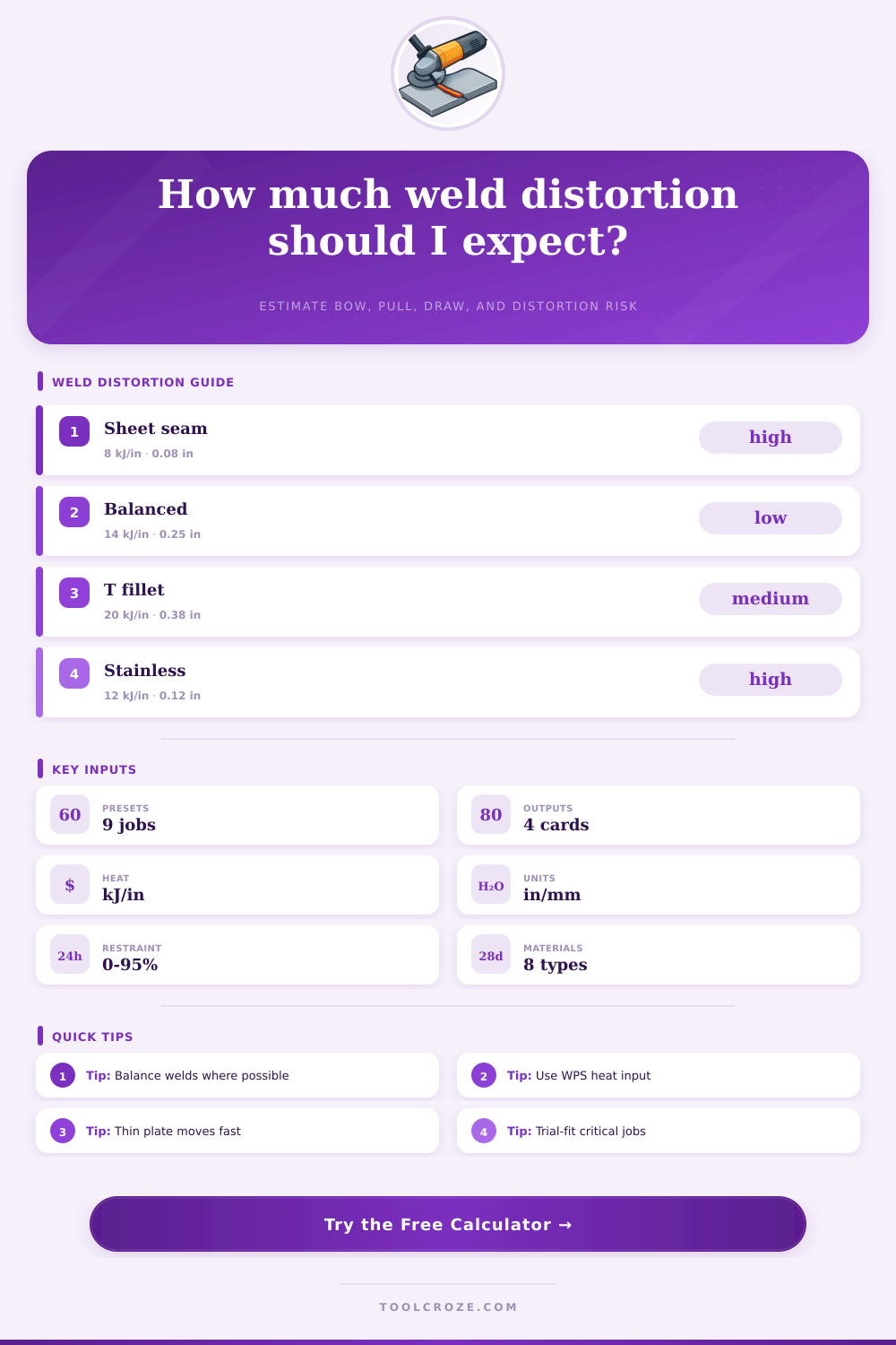
Pick a common fabrication scenario. Each preset fills heat input, length, plate thickness, restraint, material, symmetry, and shrink factor.
| Material | Expansion behavior | Factor | Distortion note |
|---|---|---|---|
| Mild steel | baseline carbon steel | 1.00 | Good reference for typical shop weld planning. |
| HSLA steel | similar expansion, tighter control | 0.95 | Usually welds like steel, but heat limits may be stricter. |
| 300 stainless | high expansion, low conductivity | 1.38 | Often shows more angular and longitudinal distortion. |
| Aluminum alloy | high expansion, high conductivity | 1.22 | Moves readily; fixturing and balanced sequence matter. |
| Chrome-moly | controlled heat procedure | 1.08 | Distortion planning should follow the qualified WPS. |
| Nickel alloy | high heat sensitivity | 1.32 | Use conservative shrink factors and shorter segments. |
| Symmetry mode | Typical use | Angular factor | Planning comment |
|---|---|---|---|
| Single-side weld | fillet, lap, corner | 1.00 | Highest angular tendency because contraction is offset. |
| Balanced both sides | double fillet, double groove | 0.48 | Balances shrinkage around the neutral axis. |
| Backstep or skip | long seams | 0.72 | Reduces accumulated pull in one direction. |
| Intermittent stitch | sheet and light frames | 0.66 | Lower total heat, but local scallop movement can remain. |
| Opposed frame welds | box frames and rails | 0.58 | Pairs welds so each side partly cancels the other. |
| Control lever | Calculator field | Direction | Distortion effect |
|---|---|---|---|
| Reduce heat input | Heat input | lower kJ per length | Usually lowers all distortion outputs. |
| Increase thickness | Plate thickness | higher stiffness | Reduces angular bow and transverse pull. |
| Balance welds | Joint symmetry | both sides or opposed | Strongly reduces angular distortion. |
| Use restraint | Restraint level | higher fixture hold | Reduces movement but increases residual stress concern. |
Weld distortion occur as soon as the weld bead cools. Weld distortion occurs due to metal contracting unevenly. When metal contracts unevenly, the metal plate or the metal frame will begin to move in ways that were not part of the original drawings.
Many metal fabrication shop experience weld distortion when a long weld seam causes an edge of the metal to pull upward. Many metal fabrication shops also experience weld distortion when the frame becomes twisted such that the vehicle’s door no longer fit into the frame. It is important for fabricators to understand that weld distortion is a predictable phenomenon.
Why Welds Change Shape and How to Prevent Them
By understanding the factor that contribute to weld distortion, fabricators can better plan their jobs and avoid surprises. One of the factors that contribute to weld distortion is the heat input into the weld joint. The higher the input of heat into the joint, the more energy that is delivered to each inch of the metal.
The more metal that expand due to heat input, the more that metal will contract as that metal cools. Thus, high heat input into thin sheet metal will cause the metal to move more than the same heat input into thick metal plate. Thus, the thickness of the metal is another factor that needs to be taken into consideration.
Another of the factors that contribute to weld distortion is the choice of metal for the sheet. One of the variables in the calculation of weld distortion is the fact that stainless steel expand more than mild steel. Additionally, stainless steel conducts heat more slow than mild steel.
Aluminum metal expands at a faster rate than stainless steel yet conducts heat very quickly. These factor affect the setting of the material factor in the calculator for weld distortion, enabling one to compare the weld distortion between metal trays made of stainless steel to metal frame made of mild steel. The type of joint that is formed and the welding sequence have an effect upon the amount of weld distortion that occurs.
Single-side fillet welds experience more weld distortion than double fillet welds. Additionally, opposed welds on metal frames will cancel each other out if applied in a welding sequence that maintains even heating of the metal. These options for symmetry allow for the welding sequence to be tested virtual in the calculator without having to create test pieces.
One of the factors that is often misinterpreted as having an effect upon weld distortion is the use of clamps and fixture to restrain the metal while welding. While the use of these tools can prevent the metal from moving during the welding process, the metal will develop internal stress due to the restraining of its contraction. When the metal is released from these fixtures, the metal will experience movement due to the release of that internal stress.
Thus, the restraint field for weld distortion will allow for a user to set a value for the distortion that is visible while welding, yet also one that will increase the stress on that metal. Metal seam that are long require special considerations regarding welding procedures. Long seams will not move as a single unit.
Ribs, tacks, or other feature of the metal frame will break up the long seam. Each of these segmented portion of metal will contract and distort independently of the other segments of the long seam. Thus, individuals must ensure that the length of the weld joint entered into the calculator is the length of the longest segment of metal that will move independently of the other segments.
The outputs for each of these calculation will enable the fabricator to make a decision regarding the welding sequence that should be used. The angular bow output will show the degree to which the edge of the metal will lift. The transverse pull will indicate the amount of movement of the joint.
Longitudinal draw will show the amount of shortening of the metal along the weld seam. The risk score will indicate the metal risk factor based on the material and the amount of restraint applied to the metal during welding. Each of these measurements will provide an estimation of the weld distortion that will occur.
However, the measurements will not account for exact dimension of the welded metal. These estimations will provide the fabricator with a better understanding of which welding sequence to test. A common mistake among metal fabricators is treating heat input as a fixed value.
Changing the amperage that is introduced into the weld joint or by changing the welding speed can reduce the contraction forces. By using the calculator, metal fabricators can determine the effect of lowering the heat input prior to making any change to the welding process. By comparing these two values, metal fabricators can determine if changing the parameter of the welding process will reduce the level of weld distortion to an acceptable level.
There are preset welding sequence that the calculator can load for common welding situations. These presets can be used for thin sheet stitch seams, balanced butt welds on metal plate, and T-joints with single fillets. These presets will provide a starting point for the welder.
The parameter for each of the metals and symmetry modes can be adjusted after loading a preset program. The reference table for weld distortion provide additional information for the fabricator regarding the interaction of each of these variables. By referring to these tables, the fabricator can better determine if the change to a welding parameter will create the desired effect on the weld.
The distortion calculator can be used during the planning stage of a fabrication job. By running scenario prior to beginning welding, metal fabricators will be able to decide which variables has the largest effect upon the weld distortion on their specific joint. It is possible that the fabricator can determine that changing from single-side welding to balanced welding will have the greatest effect upon the reduction in weld distortion.
In another scenario, it may be beneficial to increase the level of restraint yet allow for welding of the metal joint, and measuring the welded metal after the metal cools and the clamps are released. By using the weld distortion calculator, metal fabricators can have a starting point for their job. Thus, weld distortion will never be completely eliminated from metal fabrication job.
However, by using the parameter and variables of the calculator, metal fabricators can avoid surprises during the fabrication process.