Pipe Welding Calculator
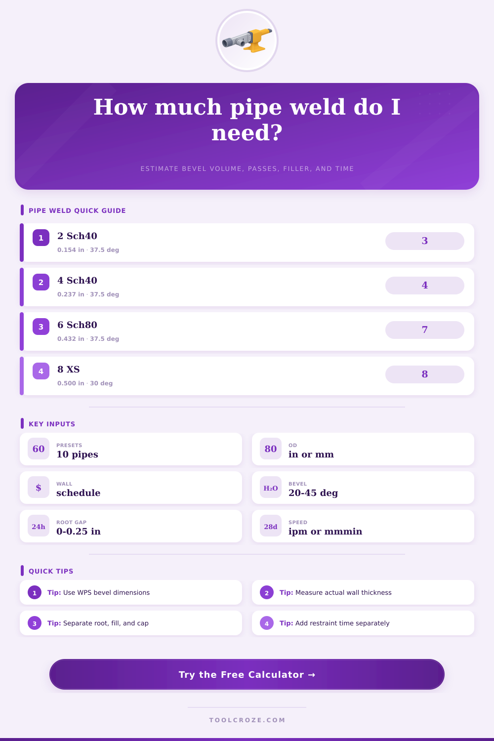
Estimate pipe weld volume, groove area, passes, filler metal, travel speed time, and root opening from pipe OD, schedule, wall thickness, bevel angle, and process inputs.
| Pipe size | Outside diameter | Schedule / wall | Typical pipe weld use |
|---|---|---|---|
| NPS 2 Sch 40 | 2.375 in / 60.3 mm | 0.154 in / 3.91 mm | Small bore process piping and vents |
| NPS 3 Sch 40 | 3.500 in / 88.9 mm | 0.216 in / 5.49 mm | Utility and process spools |
| NPS 4 Sch 80 | 4.500 in / 114.3 mm | 0.337 in / 8.56 mm | Steam, pressure, and threaded branch work |
| NPS 6 Sch 40 | 6.625 in / 168.3 mm | 0.280 in / 7.11 mm | Common field butt weld size |
| NPS 6 Sch 80 | 6.625 in / 168.3 mm | 0.432 in / 10.97 mm | Heavy wall fill and cap planning |
| NPS 8 XS | 8.625 in / 219.1 mm | 0.500 in / 12.70 mm | High pressure pipe and nozzles |
| Joint detail | Bevel angle | Root opening | Calculator effect |
|---|---|---|---|
| Open root V-groove | 30-37.5° per side | 1/16-1/8 in | Root gap adds rectangular volume at the land |
| Heavy wall narrow gap | 20-30° per side | 1/8 in typical | Less bevel volume but more controlled passes |
| Compound bevel | 37.5° near root | WPS controlled | Use average included fill width for planning |
| Cap reinforcement | Not bevel based | Beyond OD width | Modeled as a shallow cap bead around OD |
| Root face / land | Flat root land | Usually 1/16 in | Reduces bevel height before tangent width |
| Process | Typical pipe role | Deposition range | Travel speed range |
|---|---|---|---|
| GTAW / TIG | Root pass and stainless pipe | 0.8-3 lb/hr | 2-7 in/min |
| SMAW stick | Root, hot pass, fill, and cap | 2-6 lb/hr | 3-9 in/min |
| GMAW / MIG | Shop spool and roll welding | 4-10 lb/hr | 8-20 in/min |
| FCAW | Field fill and cap passes | 6-14 lb/hr | 6-16 in/min |
| SAW | Rotated shop pipe or vessel seams | 15-35 lb/hr | 15-35 in/min |
| Wall range | Common pass split | Planning check | When to refine |
|---|---|---|---|
| Under 0.188 in | Root plus cap | 2-3 passes | Thin wall heat input controls dominate |
| 0.188-0.375 in | Root, hot, fill, cap | 3-5 passes | Separate root speed from fill speed |
| 0.375-0.625 in | Root, hot, several fills, cap | 6-10 passes | Use layer-by-layer bead dimensions |
| Over 0.625 in | Controlled fill sequence | 10+ passes | Check WPS heat input and interpass limits |
| Branch or nozzle | Varies around saddle | Segment joint | Calculate long and short sides separately |
Pipe welding require that a person perform an accurate calculation of the volume of weld metal that a person must lay down into the joint. If a person dont calculate the volume of weld metal that is required to join the two end of the pipe, then a person may either run out of weld metal or have to add more pass to the welded joint than the calculations indicated. The volume of weld metal that is required to join the two ends of an pipe is calculated through a consideration of the physical dimension of the pipe.
The outside diameter and the thickness of the wall of the pipe will affect the area of the joint that is to be welded. The bevel angle of the joint may differ according to the thickness of the pipe; thick walled pipes may have different bevel angles than light-walled pipes. Additionally, the root face and root gap will add to the volume of weld metal that is required to join the two ends of the pipe; each subsequent pass must be made onto this initial volume of weld metal.
How to Calculate Weld Metal Volume for Pipes
Welding process will affect the volume of metal that can be placed into the joint. For instance, processes with high rates of metal deposition may result in large area (or beads) of weld metal. These large areas may lead to entrapment of slag within the weld or lack of fusion between the metal ends being joined.
Additionally, if the metal travel slowely along the joint, the arc will be on for longer period of time. Welding with slow travel speeds will be less efficient than welding with fast travel speeds. Thus, the welding process will affect the volume of weld metal required.
Another consideration of the volume of weld metal is the density of the metal. For example, carbon steel and nickel alloy metal has different densities. Thus, the density of the metal will impact the weight of the weld metal that is required to be ordered to join the two ends of the pipe.
The calculator will adjust for the density of the metal; it will adjust for metal density so that the calculation of the volume of weld metal is accurate regardless of the metal that is to be welded. Pipe size come in different sizes and thicknesses. The thickness of the wall of the pipe may change after facing or counterboring the pipe ends.
Because of this, any change in the thickness of the pipe will impact the volume of weld metal that is required. Tables exist with information regarding the thickness of the wall of the pipe according to the pressure class of the pipe. These tables can also be used to estimate the number of weld passes that will be required.
The number that is calculated with the weld metal volume calculator should of been compared to the welding procedure that is qualified for the joint of pipes. If the average area of weld metal per pass is too large, the weld volume may be split into root, fill and cap segment. The calculation of travel time and deposition time together can help to determine the time that will be required for welding the joint; travel time and deposition time will only account for the arc-on time of welding the joint.
The service condition of the joint of pipes will change the parameters that is entered into the calculator. Low-pressure vent lines have different service conditions than pressure vessel nozzles. Narrow-gap pipe preparations will reduce the amount of weld metal that is required for the joint.
Narrow gaps require that each layer of welding be of high quality. Compound bevels add complexity to the calculation of the weld area but may provide better access to the weld area on heavy wall pipes. A factor is used in the calculator that accounts for these different type of joint preparations.
Before welding is begun, the thickness of the metal wall and the bevel angle must be measured to ensure that the calculations regarding the volume of weld metal are accurate. Using a calculator to determine the volume of weld metal will ensure consistency in the metal that is used and the welding processes that are performed.