Fusion Welding Calculator
Estimate joint volume, heat input, travel speed, process efficiency, filler mass, cooling risk, and pass count for common arc and high-energy fusion welding setups.
⚙ Named fusion welding presets
Choose a shop scenario, then adjust the joint, process, heat, travel, and filler inputs for your weld procedure estimate.
📏 Weld joint, process, and heat inputs
Calculation breakdown
🧰 Selected process and material grid
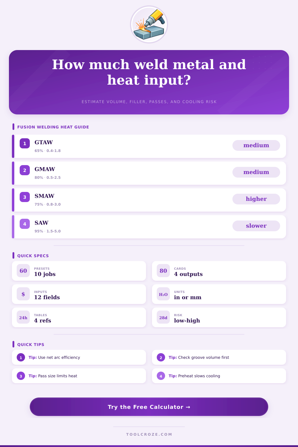
📊 Process efficiency reference
| Process | Typical efficiency | Useful heat input range | Planning note |
|---|---|---|---|
| GTAW / TIG | 55 to 75 percent | 0.4 to 1.8 kJ/mm | Precise heat, lower deposition rate |
| GMAW / MIG | 75 to 85 percent | 0.5 to 2.5 kJ/mm | Balanced deposition and travel speed |
| SMAW / stick | 65 to 80 percent | 0.8 to 3.0 kJ/mm | Rod stubs and slag reduce deposit yield |
| FCAW | 75 to 88 percent | 0.8 to 3.5 kJ/mm | High fill rate, watch interpass heat |
| SAW | 90 to 99 percent | 1.5 to 5.0 kJ/mm | Deep heat input and high deposition |
| Laser beam | 35 to 60 percent | 0.05 to 0.6 kJ/mm | Narrow fusion zone, fast cooling |
📐 Joint volume reference
| Geometry | Main input | Area model | Best use |
|---|---|---|---|
| Fillet weld | Leg size | 0.5 x leg x leg plus cap | Frames, brackets, lap corners |
| Square butt | Thickness and gap | gap x thickness plus cap | Autogenous and thin seams |
| Single V-groove | Depth and angle | gap x depth plus V area | Plate and pipe groove welds |
| Double V-groove | Depth and angle | about 55 percent of single V | Thick plate with backgouging |
| Lap seam | Seam width | width x fusion depth | Sheet, laser, resistance-adjacent seams |
🌡 Cooling risk and preheat reference
| Material group | Cooling sensitivity | Heat input watch point | Preheat clue |
|---|---|---|---|
| Mild steel | Low to medium | Low heat can harden thick restraint | Often ambient for thin sections |
| Low alloy steel | Medium to high | Hydrogen cracking risk rises with fast cooling | Preheat often procedure controlled |
| Stainless steel | Distortion sensitive | High heat raises distortion and metallurgical risk | Use interpass limits from WPS |
| Aluminum | High conductivity | Needs travel speed balance and cleaning | Moderate preheat for thick parts |
| Titanium | Shielding sensitive | Color and backside shielding matter | Control contamination, not just heat |
📝 Filler and pass planning reference
| Filler process | Deposit efficiency | Pass area guide | Planning note |
|---|---|---|---|
| Autogenous TIG or laser | No filler | Small fused seam | Mass result shows fused metal only |
| Solid wire GMAW | 85 to 95 percent | 0.035 to 0.090 sq in | Good baseline for fillets and grooves |
| SMAW electrode | 55 to 75 percent | 0.025 to 0.070 sq in | Allow for slag, stubs, and restarts |
| FCAW wire | 75 to 90 percent | 0.060 to 0.140 sq in | Useful for high fill structural work |
| SAW wire and flux | 90 to 98 percent | 0.120 to 0.300 sq in | Large pass volumes need heat control |
💡 Fusion welding calculation tips
A fusion welding calculator is a welding tool that help welding professionals calculate welding variables prior to beginning the welding process. These variables include the amount of filler metal that is require for welding, the number of passes that will be required to complete the weld, and the effect that the welding process will have upon the metal being welded. By using a fusion welding calculator prior to welding, professionals can reduce the amount of time that they spend welding and correcting welding mistakes.
Inputs for a fusion welding calculator include information such as the joint geometry, the material thickness, and the welding process that is to be performed. Joint groove angles and root gaps is two variables that is considered for fusion welding calculations because these variables will change the volume of the space to be filled by the weld metal. The thickness of the metal that is to be welded and the size of the weld will also impact the volume of the space that has to be filled by the weld metal.
What a Fusion Welding Calculator Does
Additionally, travel speed, voltage, and amperage are three variables that is considered for fusion welding calculations. Process efficiency is also one of the variables for fusion welding calculations. Each of these variables has the potential to impact the amount of filler metal that is used, the number of passes that is required to complete welding the metal, and the cooling rate of the metal after welding.
Heat input is a critical element to fusion welding calculations. The amount of heat that is input into the weld will impact the microstructure of the metal. Using too little heat can cause the metal to crack.
Using too much heat into metals like aluminum or stainless steel can cause those metals to warp. Heat input can also be used to calculate the net heat that will be input into the weld; this value will help determine whether or not preheat or interpass temperature settings should be adjusted prior to welding. The pass planning process determines the number of layers of weld metal that will be applied to the metal joint.
Fusion welding calculations include the target pass area that will be used to calculate the number of layers of weld metal that are necessary to fill the joint. The target pass area will have to be adjusted based off the welding position and the thickness of the metal. Target pass area is a critical variable in fusion welding calculations because too large of a target pass area may cause welding difficulty during the welding process.
Metals that have high conductivities, such as copper or aluminum, will draw heat away from the joint at a faster rate than metals like mild steel. Process inputs and settings that is used for mild steel will not necessarily work for copper or aluminum joints. Metals with low degrees of alloying, such as low-alloy steels, require slower cooling rates than other metals.
Fusion welding calculations will include an indicator of the risk of excessive cooling of the metal joint; this will consider the sensitivity of the metal to cooling rates, the heat input into the joint, the thickness of the metal, and the preheat settings for that metal. While a fusion welding calculation cannot replace the procedure qualification record for welding procedures, the fusion welding calculator can alert the welder to metals and metal combinations that may require more attention during the welding process. Deposition efficiency is a calculation that considers the cost of the filler metal and the time spent welding.
Autogenous welding processes will have a deposition efficiency of 0 because there is no use of filler metal in these processes. Solid wire welding processes will have a modest deposition efficiency. Covered electrode welding processes will have a lower deposition efficiency rate than other welding processes.
Fusion welding calculations will take into account the deposition efficiency for each welding process; this will allow the calculations to provide an estimate of the amount of filler metal that will be used during the welding process. Travel speed is one of the welding variables that can alter the heat input into the joint, the size of the weld metal beads, and the productivity of the welding process. High travel speeds will reduce the amount of heat and weld bead size; however, high travel speeds can lead to lack of fusion and undercut defects.
Low travel speeds will increase the heat and the size of the weld passes that can be made in one welding pass. However, low travel speeds can lead to burn-through of thin metal section and an excessive heat affected zone. Fusion welding calculations will indicate the effects that different travel speeds will have on the welding process.
Errors can occur in the welding process if only one variable is controlled while others are changing. For example, the same travel speed can be used for vertical welding joints as for flat welding joints, but vertical welding joints require smaller weld metal diameters. Another example of an error is when preheat settings are not adjusted for thick metals that have low degree of alloying.
Thick metals with low degrees of alloying exhibit specific preheat requirements. Additionally, another error in the welding process is to use the efficiency of the welding machine instead of the efficiency of the welding process; this will have an impact upon the heat input into the weld metal. The reference tables included with fusion welding calculations help to decide the appropriate settings and values for each welding variable.
The process efficiency tables indicate the amount of heat that will be transferred to the metal after heat is lost to the welding torch and radiation. Joint geometry tables include the methods for calculating the volume of metal that will be welded based on the shape of the joint. Cooling sensitivity tables include information regarding metals with high cooling rates that require specific welding variables to be controlled.
These tables will help welders to make informed decisions regarding the settings and variables for each welding process. However, these tables dont replace a qualified welding procedure specification. A fusion welding calculator cannot account for all of the variables that may occur during the welding process.
The variables that may impact the welding process but are not included in the fusion welding calculator may include fit-up, shielding gas quality, and welding skill. A joint that passes the fusion welding calculator may not have the proper root gap for adequate fusion of the metal sections. Welding professionals must use a test coupon prior to welding the welded joint to ensure that the joint will weld properly.
First performing the fusion welding calculations will allow welders to determine the amount of filler metal that will be used and the number of passes that will be required for metal welding. Its important to use modern tools for accuracy. Youll find that a fusion welding calculator is much more reliabel than manual math.
When you are working with alot of metal, you should of used a calculator.