Spot Welding Calculator
Estimate resistance spot welding current, weld time, nugget diameter, electrode force, pitch spacing, heat balance, and setup warnings for sheet metal lap welds.
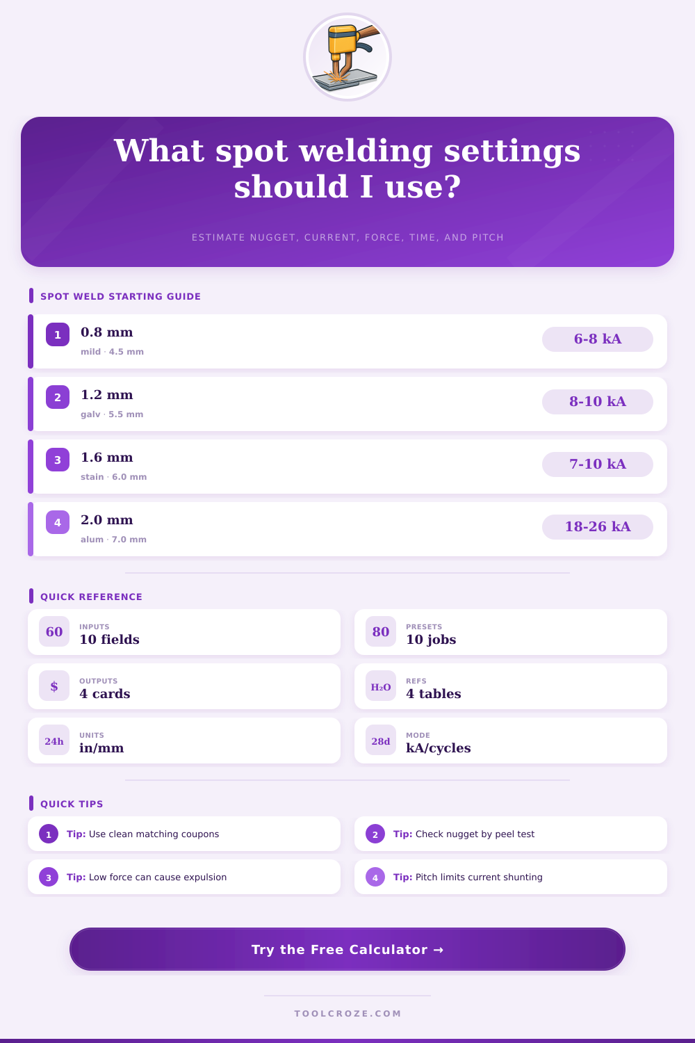
Choose a common sheet metal schedule. Each preset fills the calculator and runs the weld setup estimate.
Spot welding setup result
Calculation breakdown
| Material | Typical sheet range | Current behavior | Schedule note |
|---|---|---|---|
| Low carbon steel | 0.5 to 3.0 mm | Moderate current | Most forgiving; verify nugget by peel or chisel testing. |
| Galvanized steel | 0.6 to 2.5 mm | Higher current | Zinc coating needs more heat and frequent electrode dressing. |
| Stainless steel | 0.4 to 2.0 mm | Shorter pulse | Higher resistance can overheat; watch indentation and discoloration. |
| Aluminum sheet | 0.8 to 3.0 mm | Very high current | Needs high-current equipment, clean surfaces, and stable force. |
| Nickel strip | 0.1 to 0.4 mm | Low energy | Use short pulses and test pull strength on matching coupons. |
| Thickness per sheet | Steel nugget target | Steel current range | Common weld time |
|---|---|---|---|
| 0.6 mm / 0.024 in | 3.5 to 4.0 mm | 4.5 to 6.5 kA | 6 to 10 cycles at 60 Hz |
| 1.0 mm / 0.039 in | 4.5 to 5.0 mm | 6.5 to 9.0 kA | 8 to 14 cycles at 60 Hz |
| 1.6 mm / 0.063 in | 5.8 to 6.5 mm | 8.0 to 12.0 kA | 10 to 18 cycles at 60 Hz |
| 2.0 mm / 0.079 in | 6.5 to 7.2 mm | 10.0 to 14.0 kA | 14 to 24 cycles at 60 Hz |
| 3.0 mm / 0.118 in | 8.0 to 9.0 mm | 13.0 to 18.0 kA | 20 to 34 cycles at 60 Hz |
| Electrode face | Best use | Force tendency | Watch point |
|---|---|---|---|
| 3 to 4 mm | Thin sheet and small tabs | Lower force | Easy to overheat if current is not reduced. |
| 5 to 6 mm | Automotive sheet steel | Moderate force | Common starting face for 0.8 to 1.6 mm steel. |
| 7 to 8 mm | Heavier sheet and coated steel | Higher force | Needs enough current to form the nugget. |
| 10 mm plus | High current aluminum | High force | Machine capacity and tip cooling become critical. |
| Layout rule | Common minimum | Why it matters | Calculator check |
|---|---|---|---|
| Pitch spacing | 6D to 8D | Close welds steal current through the previous nugget. | Spacing input compared with nugget diameter. |
| Edge distance | 3D to 4D | Too close to edge can cause expulsion and weak buttons. | Shown in the breakdown as an edge target. |
| Row offset | Half pitch | Staggered rows reduce local heat concentration. | Use the calculated pitch before laying out rows. |
| Coupon testing | Every setup | Actual machines, tips, coatings, and fit-up change results. | Compare button size with target nugget. |
| Defect signal | Likely cause | First adjustment | Second check |
|---|---|---|---|
| No button on peel test | Low heat or poor contact | Raise current or time slightly | Clean sheets and check force. |
| Metal expulsion | Too much heat or low force | Raise force or reduce current | Check fit-up and tip alignment. |
| Deep indentation | Small face or high force | Dress tip to correct diameter | Review current and hold time. |
| Inconsistent nuggets | Tip wear or coating variation | Dress electrodes regularly | Keep squeeze and hold stable. |
Spot welding is a process that is used to join two piece of metal together. Spot welding is used in a variety of applications, such as battery packs, and even for forming roof rails upon which truck may place there cargo. A spot weld itself is formed by placing two sheet of metal between two electrodes, and passing an electrical current through the sheets of metal.
The electrical current heats the metal sheets until they melts, at which point the two sheets of metal will naturaly bond together. Any imbalance in the parameters for the spot weld will result in the spot weld being weak or the welding process fail altogether. The electrical current that is required to form a spot weld is dependent upon a few different factors.
Spot Welding Basics and Settings
For example, the thickness of the metal sheets that are to be welded will require more amperage to heat the middle of the sheets to the melting point. However, if the amount of current is too great, expulsion of the melted metal from the weld will occur. Expulsion will result in both a weak weld and an unattractive weld.
The calculator tool provides a range of starting values for the current, as the exact current necessary for a spot weld is not always accurate. However, providing a range of potential values for the current allows for adjustments to the setting based off the actual welding condition in the shop. Another factor in the spot welding process is the time that the welding occur.
Weld times for thin sheets of steel may be short, but thicker sheets of metal may require longer periods of welding. If long periods of welding occur with no application of sufficient force to the sheets of metal, however, the metal will become overheated. Weld times are provided in both cycles and milliseconds, as weld times need to match the capabilities of the welding machine.
Force in the spot welding process is another variable that is often underappreciated. The welding electrodes must be strong enough to break apart the naturally-forming oxides on the sheets of metal, but if too much force is applied with the electrodes, the weld nugget will be flattened. The diameter of the weld nugget will be smaller with excessive force applied to the weld.
The calculation provides a target force according to the thickness of the metal sheets and the size of the electrode face. The force of the welding electrodes should remain within the indicated range within the calculation. The spacing between spot weld is a third constraint of the spot welding process.
If the spot welds are too close together, the electrical current will travel through the existing weld spot rather than through the spot where the next weld spot will be formed. This movement of the electrical current away from the spot where heat is needed will result in cooler metal at that spot. The minimum distance between spot welds should increase with the increasing diameter of the weld spot.
The calculation will flag the spacing between spot welds if it is too small. Small distances between spot welds will cause inconsistent spot welds. The type of metal that is used for the sheets also play a role in the spot welding process.
For instance, low-carbon steels are more easily welded than metals that contain more carbon. Steels that are coated in zinc will require more electrical current to weld than metals that do not contain coatings of zinc, as the zinc will react with the electrode metals. Metals that contain less metal conductivity than mild steel will require shorter welding times to prevent the overheating of the metal sheets.
Metals like aluminum will require higher amounts of current and the metal sheets must be very clean for welding to occur. The size of the electrode face will impact the spot welding process. Electrodes with smaller face sizes will concentrate the heat needed to melt the metal sheets.
Small electrode faces wear down more quickly, however, as they create indentations in the metal sheets. Electrodes with large face sizes will distribute the force applied to the metal sheets by the electrode over a larger area. The benefit of large face sizes of the electrodes is that they will last longer when welding metal sheets that contain coatings.
However, the large face sizes will require more force to maintain the same amount of pressure on the sheets of metal. The tables provided as a reference may help to compare the size of the electrode face with the force requirements for the metal sheets. The conditions in which the welding occurs will differ from the conditions described in the laboratory.
For instance, metal sheets may contain variations in thickness, coating, and the wear on the electrodes. These variations will impact the outcomes of the welding process. The calculations provide a match score to compare the entered specifications of the welding process with the calculated specifications for the process.
High scores indicate that the specifications entered into the weld are close to the target specifications for the welding process, but actual testing is still required to prove the quality of the weld. The spot welding process calculator is used as a means of reducing the number of spot welds that must be attempted before reaching an acceptable weld. However, the calculator cannot replace actual testing.
If a peel test of a weld spot reveals no weld nugget, this indicates that there was not enough heat applied to the spot weld or that there was a problem in the contact between the metal sheets. If expulsion is present at a weld spot, this indicates that there was too much current or that there was not enough force applied during the welding process. Deep indentations into the metal sheets may be the result of using an electrode with too large of a face size or applying too much force to the sheets.
If the spot welds created are not consistent with one another, the electrode tips may be worn or the spot weld spots may have changed in their condition. The weld calculation process provides warnings that will allow for the adjustment of one of these variable to fix the issue indicated in the spot weld. Spot welding has a few limits as to its safety and the specifications of the welding machine that will perform the weld.
For example, ventilation is necessary when welding sheets of steel that contain coatings. Pinch hazards can occur when applying high force to the sheets of metal. The welding machine must have appropriate cooling capabilities to handle the weld, as well as enough power to perform the spot weld.
The calculation specifies settings that should be matched with the specifications of the welding machine to be used. By using the calculation properly, the calculation will assist in the welding process in that it will allow for the spot weld to be formed at a more rapid rate then would of otherwise occur with trial and error methods for forming the weld.