Flux-Cored Welding Calculator
Estimate FCAW deposition rate, heat input, wire use, travel-speed balance, stickout effect, and arc time from wire diameter, shielding mode, WFS, voltage, and flux efficiency.
⚙Units and named FCAW presets
Presets are planning examples for common flux-cored wires. Confirm actual ranges with the wire data sheet, machine chart, and qualified WPS.
🔧Flux-cored welding inputs
Flux-cored welding result
📊FCAW result cards at a glance
📘Flux-cored welding reference tables
| Wire size | Typical mode | Common WFS window | Voltage window | Stickout target |
|---|---|---|---|---|
| 0.030 in / 0.8 mm | Self-shielded sheet wire | 60 to 170 ipm | 14 to 18 V | 1/2 to 3/4 in |
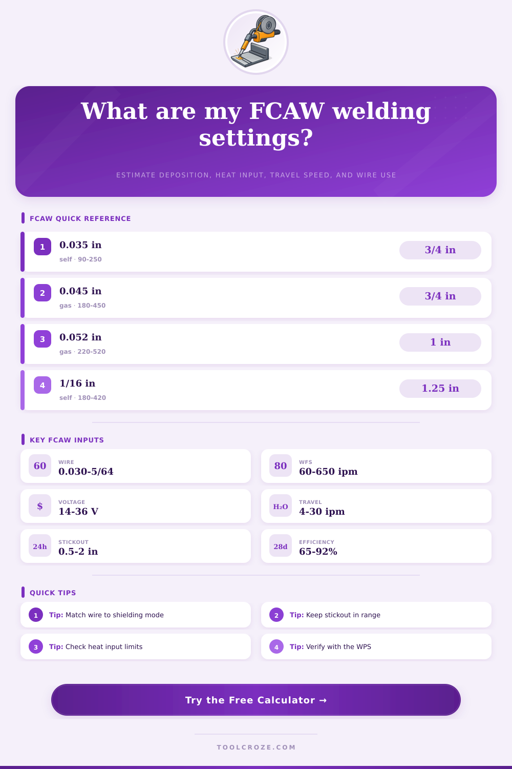
| 0.035 in / 0.9 mm | E71T-GS or E71T-11 | 90 to 250 ipm | 15 to 20 V | 5/8 to 7/8 in |
| 0.045 in / 1.2 mm | FCAW-G or FCAW-S | 180 to 450 ipm | 21 to 29 V | 3/4 to 1-1/4 in |
| 0.052 in / 1.4 mm | Structural FCAW | 220 to 520 ipm | 23 to 31 V | 7/8 to 1-3/8 in |
| 1/16 in / 1.6 mm | Heavy self-shielded | 180 to 420 ipm | 24 to 32 V | 1 to 1-3/4 in |
| 5/64 in / 2.0 mm | High deposition flat work | 250 to 550 ipm | 26 to 34 V | 1 to 1-1/2 in |
| Shielding mode | Typical efficiency | Arc behavior | Useful output check | Practical note |
|---|---|---|---|---|
| FCAW-G, CO2 | 82 to 88% | Deep penetration, more spatter | Heat input and bead shape | Good for structural carbon steel with gas coverage. |
| FCAW-G, 75/25 | 84 to 90% | Smoother arc and puddle | Voltage and travel speed | Common shop setup for all-position rutile wires. |
| FCAW-S E71T-8 | 72 to 82% | Longer stickout, slag support | Stickout and polarity | Used in field welding where wind makes gas shielding difficult. |
| FCAW-S E71T-11 | 65 to 78% | Low gas need, more slag | Duty cycle and burn-through | Best kept within the wire maker thickness range. |
| Stainless FCAW-G | 78 to 86% | Fluid puddle, chromium control | Heat input limit | Follow stainless interpass and shielding requirements. |
| Variable | If increased | Main result change | Watch for | Calculator cue |
|---|---|---|---|---|
| Wire feed speed | More electrode per minute | Higher current and deposition | Undercut or excess spatter | Deposition card rises quickly. |
| Voltage | Longer arc and flatter bead | Higher heat input | Porosity, spatter, wide bead | Heat input card increases. |
| Travel speed | Less time per inch | Lower heat input and bead size | Lack of fusion if too fast | Bead grid value gets smaller. |
| Stickout | More resistance heating | Current may soften | Porosity or unstable arc | Range card warns out-of-window. |
| Flux efficiency | More wire becomes weld metal | Higher deposited pounds per hour | Wrong value for wire type | Deposition rate changes directly. |
| FCAW scenario | Wire and mode | Starting settings | Travel range | Shop check |
|---|---|---|---|---|
| Thin sheet repair | 0.030 E71T-11 self-shielded | 90 ipm, 16 V | 12 to 20 ipm | Control heat and skip around the joint. |
| Light bracket weld | 0.035 E71T-GS self-shielded | 160 ipm, 18 V | 8 to 16 ipm | Watch burn-through on edges and corners. |
| Structural fillet | 0.045 E71T-1 gas-shielded | 280 ipm, 25.5 V | 7 to 13 ipm | Check leg size and slag removal between passes. |
| Heavy plate fill | 0.052 E71T-1 gas-shielded | 360 ipm, 28 V | 6 to 12 ipm | Track interpass temperature and heat input. |
| Field beam weld | 0.045 E71T-8 self-shielded | 230 ipm, 24.5 V | 5 to 10 ipm | Confirm polarity, stickout, and wind exposure. |
Flux-cored arc welding allows a person to deposit metal quick into the weld site. This welding process is useful because the welding wire contain a flux-filled tubular sheath. The flux provide shielding for the weld.
This shielding will protect the weld even if there is wind or if the welder must use awkward body position to access the welding site. Many people use flux-cored welding processes to weld structural steel, field repairs, or heavy equipment. These welding tasks use flux-cored welding because it is fast.
Flux-Cored Welding and the Welding Calculator
However, flux-cored welding can be too fast for some welders to produce perfect weld. Welders can make mistakes during flux-cored welding, and these mistakes can take the form of lack of fusion or excessive heat that causes the metal joint to warp. A welder must make several decision prior to beginning the welding process.
The welder must choose the wire diameter to use. The welder can use gas-shielded wire or self-shielded wire. The welder must also choose the wire feed speed.
These welding variables impact the amount of current the welder use, the penetration of the welding rod into the metal, and the amount of electrode that becomes weld metal. Other welding variables include the stickout length of the welding rod and the travel speed of the welders welding machine head. All these variables impact one another.
A welder must calculate these variables to achieve a balance in the welding process. The calculator embedded on this page will compute the value of the welding variables after a welder enters the known welding variables. This welding calculator will determine the deposition rate of the welding metal.
It will factor in the efficiency loss from slag and spatter during the welding process. It will also provide an estimation of the heat input in the welding process. These welding outputs will allow the welder to understand if the size of the weld bead will be sufficient for the welding project.
The output will also show if the heat input of the welding process is within the code limit for the metal joint. The calculator will project the total amount of wire that will be consumed during the welding process and the length of time it will take to complete the welding job. This information will allow the welder to bid on welding jobs or to plan a welding crews time.
The diameter of the welding wire determine the maximum amount of metal a welder can melt per minute. Using a 0.035-inch welding wire will allow a welder to weld thin sheet metal. However, heavy fillets will reach the limit of the wire.
Using a 0.052-inch or 1/16-inch welding wire allow for the metal to have a higher mass flow rate. However, the voltage and the stickout length of the welding rod will increase with an increased wire diameter. Self-shielded welding rods are useful in applications where there is alot of wind because the flux within the rod will generate its own shielding gas.
However, self-shielded welding rods usually have a longer stickout length and experience lower efficiency than gas-shielded welding rods. The welding calculator accounts for the variables of the self-shielded welding rods. The heat input during welding is a measurement that fabricators monitor.
The specifications of the metal being welded set the limits of heat input. When the welder increase the voltage levels, the amount of energy delivered to the welding joint increases. However, the travel speed of the welding rod impacts how much of that energy is delivered into the metal.
If the welder increases the wire-feed speed, the current levels will increase. High levels of current is useful for welding until the molten puddle begins to undercut the metal joint. If the welder increases the travel speed of the welding rod, the energy concentration in the metal will increase.
High levels of energy will heat a larger portion of the metal joint. The welding calculator outputs the value of heat input for a welding job so the welder can adjust the welding variables to bring the heat input within an acceptable range for the metal joint. The travel speed of the welding rod impacts the size of the weld bead.
Welding with a fast travel speed will produce a weld where the center of the weld bead is proud above the metal joint, but the weld toes is cold to the touch. If the welder reduces the travel speed, the weld puddle will wash out. However, a weld puddle will only wash out if the wire-feed rate is high enough to properly fill the metal joint.
The size of the weld bead is an output of the welding calculator. This output will show whether or not the welder will achieve the required leg dimension for the weld metal joint. This information is vital for projects that require more than one pass to complete the weld joint.
The operating factor is a welding variable that is only important once welding begin. The welder may have the best welding variables set up prior to welding. However, the welder will lose time welding when repositioning the welders welding rod or removing slag from the weld metal joint.
The welding calculator applies an operating factor to the time calculated by welding variables so that the estimated time to complete the welding job reflects the actual time required. If the operating factor is low, the welder may think they can complete a job in 100 minute. However, the welding rod will take more than 100 minutes to complete the job.
The operating factor accounts for the additional minutes required by the welder to complete the welding job. Many welders make mistakes by treating welding variables as if they are independent of one another. If the welder increases the welding voltage, the heat input increase.
The increased heat may take the heat input beyond the interpass limit for the metal joint. Another welder may reduce the stickout length to increase the penetration of the welding rod into the metal joint. However, the welder may create an unstable arc in the welding rod.
The welding calculator does not replace the skill of a qualified welder. However, it will allow the welder to see the interaction of the welding variables prior to beginning welding. Field conditions can change the outcome of welding.
The wind may strip the shielding gas from the welding gas that is in the welding rod. Self-shielded welding rods can tolerate wind. However, they must have the proper polarity and stickout length for the flux within the welding rod to react to the metal joint.
The metal joint may experience changes in temperature that change how the welding metal feel to the welder and how fast it freeze during welding. These welding variables are not part of the welding calculator. However, they explain the different outcome of welding metal under the same settings on different days.
The goal in using the welding variable calculator is to understand the effect of changing one welding variable over another. For instance, if the deposition rate is low, the welder can use the calculator to see if the low rate is due to the wire diameter or the wire-feed speed. If the heat input is too high for the metal joint, the welder can use the welding variable calculator to determine if the voltage should be lowered and the travel speed increased.
The welding variable calculator makes it easy for the welder to compare the different welding variables and to decide which will be adjusted in the welding joint.