Welding Electrode Calculator
Estimate stick electrode count, deposited filler metal, arc-on time, rods per pass, and allowance from weld length, joint type, rod diameter, electrode class, stub loss, and pass count.
Select a common stick welding job, then adjust the rod yield, joint size, or allowances to match the actual procedure.
Calculation Breakdown
| Electrode Class | Typical Use | Planning Efficiency | Approx. Deposition Rate | Practical Note |
|---|---|---|---|---|
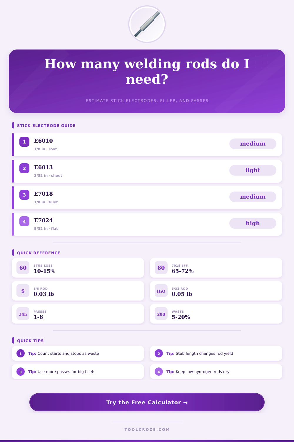
| E6010 | Root passes, pipe, open joints | 58 to 64 percent | 1.8 to 2.4 lb/hr at 1/8 in | Deep penetration, higher spatter allowance |
| E6011 | Maintenance, AC capable roots | 56 to 63 percent | 1.7 to 2.3 lb/hr at 1/8 in | Good for less-than-perfect surfaces |
| E6013 | Sheet, light plate, clean beads | 62 to 69 percent | 2.0 to 2.7 lb/hr at 1/8 in | Light slag and easy restart behavior |
| E7014 | General fabrication fillets | 68 to 76 percent | 2.8 to 3.6 lb/hr at 1/8 in | Iron powder coating improves fill rate |
| E7018 | Structural fillets and grooves | 65 to 72 percent | 2.2 to 3.0 lb/hr at 1/8 in | Store dry and control starts carefully |
| E7024 | Flat and horizontal heavy fillets | 78 to 86 percent | 4.0 to 6.0 lb/hr at 1/8 in | High deposition, limited position range |
| E308L / E316L | Stainless fabrication and repair | 58 to 66 percent | 1.6 to 2.3 lb/hr at 1/8 in | Keep heat input controlled on thin stainless |
| Diameter | Metric Size | Common Rod Length | Typical Weld Size Range | Planning Use |
|---|---|---|---|---|
| 3/32 in | 2.4 mm | 12 to 14 in | 1/8 to 3/16 in | Sheet, small fillets, short repair beads |
| 1/8 in | 3.2 mm | 14 in | 3/16 to 1/4 in | General shop fillets, roots, and caps |
| 5/32 in | 4.0 mm | 14 to 18 in | 1/4 to 3/8 in | Multi-pass plate and heavier fabrication |
| 3/16 in | 4.8 mm | 18 in | 5/16 to 1/2 in | Flat heavy fill with adequate amperage |
| 1/4 in | 6.4 mm | 18 in | 1/2 in and larger | High-output flat work on heavy sections |
| Joint Type | Area Factor Used | Where It Fits | Pass Planning |
|---|---|---|---|
| Single fillet | 0.50 x size² | T-joints and outside corners | One pass for small sizes, multi-pass above 1/4 in |
| Double fillet | 1.00 x size² | Both sides of a T-joint or lap | Split rods between sides and passes |
| Square butt | 0.85 x size² | Close-fit plate or bar edges | Allow extra if root gap is open |
| V-groove | 1.25 x size² | Prepared plate grooves | Root, fill, and cap passes raise starts |
| Hardfacing | 1.00 x size² | Wear strips and build-up layers | Use measured bead layer thickness |
When the welder begin the job, the welder must determine how many stick electrode will be required for the job. The welder needs to know the total number of stick electrodes that will be required for the weld. If the welder should run out of electrodes during one pass of welding, the welder will be forced to take a break until electrode can be purchased.
Therefore, determining the number of electrodes that will be used will help to manage the time and cost of the welding job; losing time and money is something that the welder wants to avoid. Determining the number of stick electrodes required for an weld job is more complicated than dividing the length of the weld by the length of the electrode. There are several factor that will alter the number of electrodes that will be required for a weld.
How to Figure Out How Many Stick Electrodes You Need
These factors include the geometry of the joint to be welded, the number of passes that will be used to complete the weld, and the efficiency of the stick electrode. One factor that will influence the number of stick electrodes that are required is the geometry of the joint. For example, a single fillet weld will require less metal than a double fillet weld of the same length, since a single fillet weld has only one triangular cross section that must be filled with weld metal, whereas a double fillet weld has two triangular cross sections that must be filled with weld metal.
Additionally, V-groove welds will require more weld metal than other types of joint, as the V-groove creates space within the joint for the weld metal to fill. Each of the different joint types has a specific factor associate with it within the calculator, which allows the calculator to reflect the differences in the amount of weld metal of different joint types. Another factor that will influence the number of stick electrodes that are required for a weld is the yield of metal that is provided by each stick electrode.
Not all of the metal within the stick electrodes will become part of the weld; some of the metal can be lost due to stub loss, spatter loss, and loss of metal within the electrode coating. For example, low hydrogen electrodes, such as 7018 electrodes, are more prone to these losses of metal than are some of the other types of stick electrodes. Therefore, the electrode calculation allows the welder to adjust for stub loss and allows the welder to enter a custom value for the amount of weld metal that can be deposited by each rod.
This custom value could be based off actual measurement of how much metal is deposited by each type of electrode when performing actual welding jobs. Another factor that will influence the number of stick electrodes required for a weld is the number of passes that are to be made into the joint. The more passes that are performed, the more metal will be lost when starting and stopping the weld.
For instance, three passes will require more metal than a single pass, but there will not be three times the amount of metal required for three passes as there will be for a single pass. For example, the first pass will use a different diameter of stick electrode than the remaining passes. The ability to enter the number of passes in the welding electrode calculator will allow the welder to see the total number of stick electrodes that will be required.
Additionally, the calculation will allow the welder to determine if one stick electrode will be used for all passes, or if the welder will have to change stick electrode types during the welding job. The factor of operating factor will influence the determination of the number of electrodes for another reason: to convert arc time into shop time. For example, while an electrode may have a high rate of metal deposition, the total amount of weld metal that will be completed per hour will be lower due to the need to change electrodes, remove slag, and perform other fit check.
In most welding shops, a shop uses an operating factor of 35% when performing stick welding jobs. The welding electrode calculator allows the welder to input the operating factor in order to determine the length of the welding job in terms of elapsed time. The last factor that can influence the number of stick electrodes is the waste factor.
This factor allows the welder to account for waste metal during actual jobs. For instance, stick electrodes may be wasted when welding in a weld joint that is in a clean shop; however, electrodes may be wasted when welding into an old metal frame that may be corroded. The electrode calculator includes a waste factor for each scenario, allowing the welder to enter the percentage of waste that may occur during the weld job.
The tables that are included in the welding job stick electrode calculator are another set of tools that can assist the welder in making the required calculation. Each table provides information on the efficiency of different class of electrodes, the metal deposition rate of those classes of electrodes, tables of the diameters of stick electrodes that are available, tables that provide information for different weld sizes, and a joint planning table. These tables can assist the welder in reducing the number of times that the welder has to make calculations during the welding job.
One of the most common mistakes in stick welding jobs is incorrectly calculating the amount of metal that is lost when cutting the stick electrodes into stubs. For instance, while 7018 stick electrodes require 2-inch stubs, cellulosic electrodes, such as 6010 stick electrodes, allow for shorter stubs. Because of this, if the welder makes 2-inch stubs on 7018 electrodes, the welder will use more stick electrodes during the weld than if the welder had used the calculation provided by the calculator for stick welding jobs.
However, by allowing the welder to adjust the length of the stick electrode stub in the welding stick electrode calculator, the welder can compensate for this habit. Another common mistake by welders is the fit-up of the metal joint. A joint that is fitted well and even will require less metal to create a weld than a joint that is not fitted even with the same size metals.
The welder can adjust for this using the fit-up multiplier within the welding stick electrode calculator. This will allow the welder to ensure that there is enough metal for the last pass in welding the joint. The value of calculating the number of stick welding electrodes that will be required for a job prior to beginning the welding job is that the welder can view the job as a complete system.
Each of the variables for the welding job (length of weld, size of weld, type of welding electrode, number of passes, waste) will impact each of the other variables. Therefore, the welder can determine if any adjustments must be made to any other variables than the number of stick welding electrodes that will be required. Thus, while the welding electrode calculator will not replace the experience and judgement of the welder, it will remove the math from the welders calculations, allowing the welders judgement to focus upon the weld job requirements.